Audi Q7: Differential
Left Flange Shaft, Removing and Installing
Special tools and workshop equipment required
- Hose Clip Pliers -VAS6362-
- Engine and Gearbox Jack -VAS6931-
- Ball Joint Removal Tool -T10444-
- Sealing Grease -G 052 128 A1-
 Caution
This procedure contains mandatory replaceable parts. Refer to component overview prior to starting procedure.
Mandatory Replacement Parts
- Bolts - Flange shaft mounting bracket
- Nut - Ball joint
Removing
- Drain the gear oil from front final drive. Refer to → Chapter "Gear Oil, Draining and Filling".
- Remove the left front wheel. Refer to → Suspension, Wheels, Steering; Rep. Gr.44; Wheels and Tires.
- Remove the left subframe shield. Refer to → Suspension, Wheels, Steering; Rep. Gr.40; Subframe; Subframe Crossbrace, Removing and Installing.
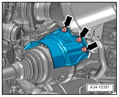
- Remove the bolts -arrows- and the left drive axle heat shield.
- Remove the left drive axle from the transmission flange shaft and move it back. Refer to → Suspension, Wheels, Steering; Rep. Gr.40; Drive Axle; Drive Axle, Removing and Installing.
- To protect the threads remove the nut -arrow- on the guide link joint pin until it is flush with the threads of the joint pin.
 WARNING
Risk of injury due to falling parts.
When removing the tie rod end is loosened abruptly from the wheel bearing housing. Place the Engine and Gearbox Jack -VAS6931- for example underneath to secure.
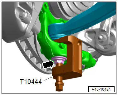
- Remove the guide link joint pin with the Ball Joint Removal Tool -T10444- from the conical seat, at the same time do not damage the CV boot.
- Remove the nut and free up the guide link on the wheel bearing housing to do so if necessary counterhold the joint pin with a TX 40 socket.
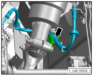
- Free up the brake hose -arrow- from the bracket and push to the side.
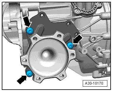
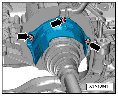
- Remove the bolts -arrows- from the flange shaft mounting bracket.
- Push the wheel bearing housing slightly forward and remove the left flange shaft at the same time on vehicles with air suspension make sure the boot has clearance to the air spring.
Installing
Install in the reverse order of removal while noting the following:
 Note
Note
- Secure all hose connections with hose clamps. Refer to the Parts Catalog.
- To installation the flange shaft further removal is required.
- Remove the subframe crossbrace. Refer to → Suspension, Wheels, Steering; Rep. Gr.40; Subframe; Subframe Crossbrace, Removing and Installing.
 Note
Note
To catch escaping coolant, place a cloth underneath.

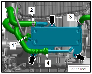
- Loosen the hose clamps -2 and 3- and then disconnect and remove the coolant hoses with Hose Clamps - Up To 25mm -3094-.
- Remove the bolts -arrows- and push the ATF cooler with the hoses -1 and 4- connected to the side.
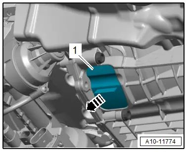
- Remove the lower cover -1- from the transmission in direction of -arrow-.
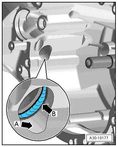
- Always clean the left flange shaft and the torque converter bell housing in the area where the differential is accessed -arrow A- and the seal -arrow B-.
 Note
Note
If the seal between the differential and transmission housing -arrow B- is damaged replace. Refer to → Chapter "Overview - Final Drive".
- Fill the space between the sealing/dust lip halfway with Sealing Grease -G 052 128 A1-.
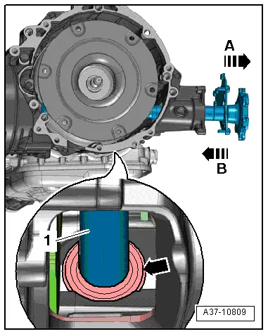
- Install the left flange shaft -1- into the transmission in direction of -arrow B-. When doing this, insert the flange shaft centrally into the seal -arrow- on the front differential.
 Caution
There is a risk of damaging the seal -arrow- between the final drive and the transmission housing from the flange shaft splines.
Keep the flange shaft centered.
 Note
Note
- A seal must be replaced if it is damaged.
- Ignore -arrow A-.
- Install the drive axle. Refer to → Suspension, Wheels, Steering; Rep. Gr.40; Drive Axle; Overview - Drive Axle.
- Install the drive axle heat shield. Refer to → Suspension, Wheels, Steering; Rep. Gr.40; Drive Axle; Drive Axle Heat Shield, Removing and Installing.
- Install the ATF cooler. Refer to → Chapter "ATF Cooler, Removing and Installing".
- Fill with coolant. Refer to → Rep. Gr.19; Coolant System/Coolant; Coolant, Draining and Filling.
- Tighten the left flange shaft mounting bracket -arrows-.
- Fill with gear oil in the transmission. Refer to → Chapter "Gear Oil, Draining and Filling".
Tightening Specifications
- Refer to → Chapter "Overview - Final Drive"
- Refer to → Suspension, Wheels, Steering; Rep. Gr.40; Lower Control Arm and Ball Joint; Overview - Lower Control Arm and Ball Joint.
- Refer to → Suspension, Wheels Steering; Rep. Gr.40; Subframe; Overview - Subframe.
- Refer to → Suspension, Wheels, Steering; Rep. Gr.44; Wheels and Tires.
Right Flange Shaft, Removing and Installing
Special tools and workshop equipment required
- Circlip Pliers -VAS5503A-
- Used Oil Collection and Extraction Unit -SMN372500-
- Slide Hammer Set -VW771- with Slide Hammer Set - Bolt -VW771/43-
- Sealing Grease -G 052 128 A1-
 Caution
This procedure contains mandatory replaceable parts. Refer to component overview prior to starting procedure.
Mandatory Replacement Parts
- Circlip - Right flange shaft
Removing
- Remove the right subframe shield. Refer to → Suspension, Wheels, Steering; Rep. Gr.40; Subframe; Subframe Crossbrace, Removing and Installing.
- Remove the bolts -arrows- and remove the heat shield from the right drive axle.
- Remove the right drive axle from the transmission and lay toward the rear. Refer to → Suspension, Wheels, Steering; Rep. Gr.40; Drive Axle; Drive Axle, Removing and Installing.
- Place the Used Oil Collection and Extraction Unit -SMN372500- under the transmission.
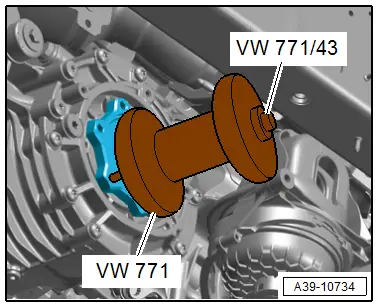
- Place the Slide Hammer Set -VW771- with Slide Hammer Set - Bolt -VW771/43- on the flange shaft, as shown.
- Remove flange shaft.
Installing
Install in the reverse order of removal while noting the following:
 Note
Note
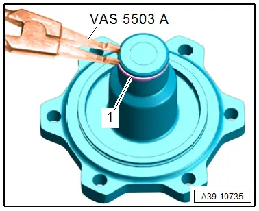
Replace the circlip after removal.
- Insert the circlip -1- with the Circlip Pliers -VAS5503A-.
- Check the right flange shaft seal for damage and replace if necessary. Refer to → Chapter "Right Seal, Replacing".
- Fill the space between the sealing/dust lip halfway with Sealing Grease -G 052 128 A1-.
- Insert the right flange shaft.
- Install the drive axle. Refer to → Suspension, Wheels, Steering; Rep. Gr.40; Drive Axle; Overview - Drive Axle.
- Install the drive axle heat shield. Refer to → Suspension, Wheels, Steering; Rep. Gr.40; Drive Axle; Drive Axle Heat Shield, Removing and Installing.
- Gear oil level in front final drive, checking and filling. Refer to → Chapter "Gear Oil, Checking Level".
Tightening Specifications
- Refer to → Suspension, Wheels Steering; Rep. Gr.40; Subframe; Overview - Subframe.

