Audi Q7: Headlamps, Calibrating
 Note
Note
Only Matrix LED headlamps must be calibrated.
Matrix LED Headlamp, Calibrating using Headlamp Adjusting Unit -VAS5209B-
Special tools and workshop equipment required
- Headlamp Adjusting Unit -VAS5209B-
 Note
Note
- The Matrix LED headlamp is calibrated. Refer to Vehicle Diagnostic Tester.
- In this procedure the low beam is set first. Then the Matrix beam high beam function is calibrated.
 Note
Note
Software version from V 0.80 for the -VAS5209B- is required to calibrate the Matrix beam high beam function.
The Matrix Headlamp Must Be Calibrated after the following Work:
- Headlamp position was changed (removing and installing, loosening and tightening the screws)
- Headlamps were adjusted.
- The Driver Assistance Systems Front Camera -R242- was replaced.
- The Drivetrain Control Module -J775- was calibrated or replaced.
- The Vehicle Electrical System Control Module -J519- was replaced.
- The Left Rear Level Control System Sensor -G76-, Right Rear Level Control System Sensor -G77-, Left Front Level Control System Sensor -G78- or Right Front Level Control System Sensor -G289- was replaced.
- The windshield was removed and installed ore replaced.
- "No or incorrect basic setting/adaptation" is stored in the DTC memory.
Requirements
- Follow the complete test and adjustment requirements. Refer to → Chapter "Headlamp, Adjusting".
Procedure
- Align the Headlamp Adjusting Unit -VAS5209B- at the distance -a- = 100 mm to the vehicle center. Refer to the Owner's Manual.

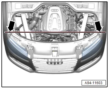
- Check the parallel alignment of the Headlamp Adjusting Unit -VAS5209B- to the vehicle transverse axis. To do so, align the laser beam of the Headlamp Adjusting Unit -VAS5209B- to the left and right front fender bolts -arrows-.
- Push the -VAS5209B- in front of the left headlamp and check the parallel alignment again.
- To prevent glare for the other motorists, pay attention to the exact orientation of the headlamp adjusting unit.
Calibrating
Vehicle Diagnostic Tester is connected.
- Select the Diagnostic mode and start.
- Select the Test plan tab.
- Press the Select individual tests button and select the following one after the other:
- Body
- Electrical Equipment
- 01 - OBD-capable systems
- 09 - Vehicle Electrical System Control Module J519
- 09 - Vehicle Electrical System Control Module functions
- 09 - Adjusting headlamps
Start the selected program and follow the instructions in the Vehicle Diagnostic Tester display. The low beam must be adjusted first for this procedure. Refer to → Chapter "LED Headlamp, Adjusting".
Further along in the program sequence a request is made to determine/read and to input the angle value of the inner segment edge of the left headlamp in the headlamp adjusting unit.
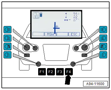
- Center the light collecting box lens to the headlamp reference segment.

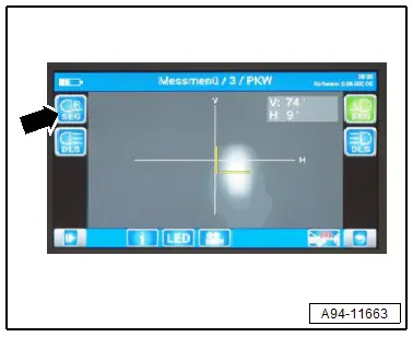
- In the main menu of the Headlamp Adjusting Unit -VAS5209B- press the "F1" button -arrow- to measure the angle value.
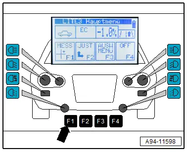
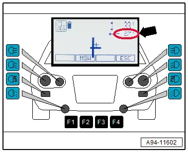
Shown on display:
- Push the button -arrow- for the left fog lamp for at least three seconds.
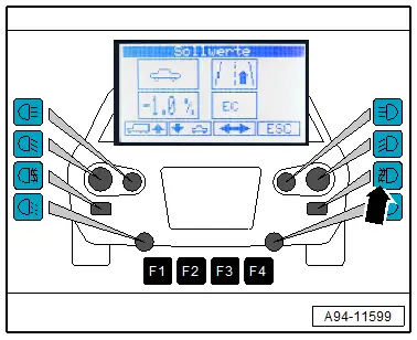
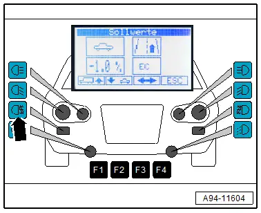
Shown on display:
- The angle values of the inner reference segment edge are displayed.
- Enter the angle value -arrow- of the inner reference segment edge in the Vehicle Diagnostic Tester. While doing so, pay attention to the sign if necessary.

- Push the "F4" button -arrow- on the Headlamp Adjusting Unit -VAS5209B-.
Further along in the program sequence a request is made to determine/read and to input the angle value of the inner segment edge of the right headlamp in the headlamp adjusting unit.

- Align the Headlamp Adjusting Unit -VAS5209B- at the distance -a- = 100 mm (3.93 in.) to the center of the vehicle. Refer to the Owner's Manual.

- Check the parallel alignment of the -VAS5209B- to the vehicle transverse axis. To do so, align the laser beam of the -VAS5209B- to the left and right front fender bolts -arrows-.
- Push the -VAS5209B- in front of the right headlamp and check the parallel alignment again.
- Center the light collecting box lens to the headlamp reference segment.
- In the main menu of the -VAS5209B-, press the "F1" button -arrow- to measure the angle value.

Shown on display:
- Push the button -arrow- for the right fog lamp for at least three seconds.
Shown on display:
- The angle values of the inner reference segment edge are displayed.
- Enter the angle value -arrow- of the inner reference segment edge in the Vehicle Diagnostic Tester. While doing so, pay attention to the sign if necessary.
- Push the "F4" button -arrow- on the Headlamp Adjusting Unit -VAS5209B-.
- After completing the calibration, read the DTC memory and correct any existing faults.
Matrix LED Headlamp, Calibrating using Headlight Adjusting Unit -VAS621001-
Special tools and workshop equipment required
- Headlight Adjusting Unit -VAS621001-
 Note
Note
- The Matrix LED headlamp is calibrated. Refer to Vehicle Diagnostic Tester.
- In this procedure the low beam is set first. Then the Matrix beam high beam function is calibrated.
The Matrix Headlamp Must Be Calibrated after the following Work:
- Headlamp position was changed (removing and installing, loosening and tightening the screws)
- Headlamps were adjusted.
- The Driver Assistance Systems Front Camera -R242- was replaced.
- The Drivetrain Control Module -J775- was calibrated or replaced.
- The Vehicle Electrical System Control Module -J519- was replaced.
- The Left Rear Level Control System Sensor -G76-, Right Rear Level Control System Sensor -G77-, Left Front Level Control System Sensor -G78- or Right Front Level Control System Sensor -G289- was replaced.
- The windshield was removed and installed ore replaced.
- "No or incorrect basic setting/adaptation" is stored in the DTC memory.
Requirements
- Pay attention to the testing and adjustment requirements. Refer to → Chapter "Headlamp, Adjusting".
Procedure
- Align the Headlight Adjusting Unit -VAS621001- at the distance -a- = 100 mm to the vehicle center. Refer to the Owner's Manual.
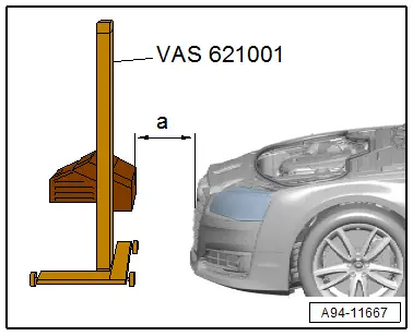
- Check the parallel alignment of the -VAS621001- to the vehicle transverse axis by aligning the -VAS621001- laser beam on the left and right front fender bolts -arrows-.
- Push the -VAS621001- in front of the left headlamp to check the parallel alignment again.
- To prevent glare for the other motorists, pay attention to the exact orientation of the headlamp adjusting unit.
Calibrating
The Vehicle Diagnostic Tester is connected.
- Select the Diagnostic mode and start.
- Select the Test plan tab.
- Press the Select individual tests button and select the following one after the other:
- Body
- Electrical Equipment
- 01 - OBD-capable systems
- 09 - Vehicle Electrical System Control Module J519
- 09 - Vehicle Electrical System Control Module functions
- 09 - Adjusting headlamps
Start the selected program and follow the instructions in the Vehicle Diagnostic Tester display. The low beam must be adjusted first for this procedure. Refer to → Chapter "LED Headlamp, Adjusting".
Further along in the program sequence a request is made to determine/read and to input the angle value of the inner segment edge of the left headlamp in the headlamp adjusting unit.
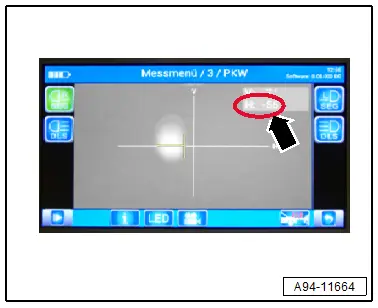
- Center the light collecting box lens to the headlamp reference segment.

- To do so press the "" button -arrow- in the main menu on the Headlamp Adjusting Unit -VAS621001- to start the measurement procedure.
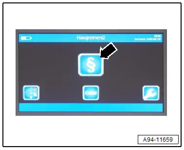
Shown on display:
- Push the button -arrow- twice and wait until the light measurement is active.
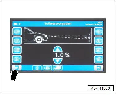
Shown on display:
- Press the button -arrow-.
- Wait until the light measurement is complete.
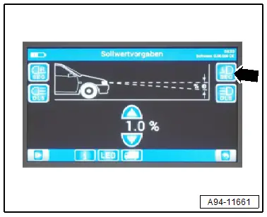
Shown on display:
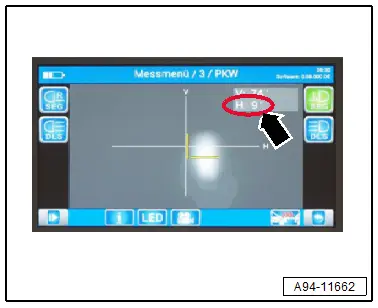
- The angle values of the inner reference segment edge are displayed.
- Enter the angle value -arrow- of the inner reference segment edge in the Vehicle Diagnostic Tester. While doing so, pay attention to the sign if necessary.
Further along in the program sequence a request is made to determine/read and to input the angle value of the inner segment edge of the right headlamp in the headlamp adjusting unit.
- Align the -VAS621001- at the distance -a- = 100 mm to the center of the vehicle. Refer to the Owner's Manual.

- Check the parallel alignment of the -VAS621001- to the vehicle transverse axis by aligning the -VAS621001- laser beam on the left and right front fender bolts -arrows-.
- Push the Headlamp Adjusting Unit -VAS621001- in front of the right headlamp and check the parallel alignment again.
- Center the light collecting box lens to the headlamp reference segment.

Shown on display:
- Press the button -arrow-.
- Wait until the light measurement is complete.
Shown on display:
- The angle values of the inner reference segment edge are displayed.
- Enter the angle value -arrow- of the inner reference segment edge in the Vehicle Diagnostic Tester. While doing so, pay attention to the sign if necessary.
- After completing the calibration, read the DTC memory and correct any existing faults.