Audi Q7: A-Pillar Trim Panel, Removing and Installing
A-Pillar Upper Trim Panel, Removing and Installing
Special tools and workshop equipment required
- Pry Lever -80-200-
- Trim Removal Wedge -3409-
- Omega Clip Tool -T40280-
Removing
- Remove the instrument panel side cover. Refer to → Chapter "Instrument Panel Side Cover, Removing and Installing".
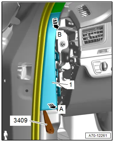
- Unclip the A-pillar gap cover -1- using the -3409- in direction of -arrow A- and disengage at the A-pillar upper trim panel in direction of -arrow B-.
 WARNING
Follow all safety precautions when working on pyrotechnic components. Refer to → Chapter "Safety Precautions for Pyrotechnic Components".

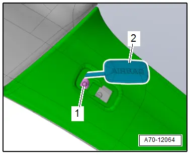
- Unclip the cap -2- with the symbol "Airbag" using a screwdriver.
- Remove the bolt -1-.
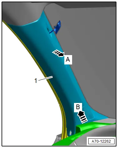
- Free up the A-pillar trim panel -1- near the door seal and disengage at the A-pillar.
- Carefully loosen the A-pillar trim panel with the -80 - 200- until the first catch loosens in direction of -arrow A-.
- Pull the trim up in direction of -arrow B- to disengage the clamps, with the hooks from the instrument panel. The clamps with slide out of the mounting point on the body.
Installing
 WARNING
- Follow all safety precautions when working on pyrotechnic components. Refer to → Chapter "Safety Precautions for Pyrotechnic Components".
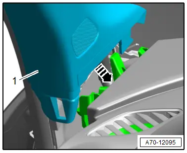
- Do not pinch the head curtain airbag when installing the upper A-pillar trim.
- Insert the A-pillar trim -1- in the mount on the instrument panel in direction of -arrow-.
Further installation is the reverse order of removal.
Installation notes, for example tightening specifications, replacing components. Refer to → Chapter "Overview - A-Pillar Trim Panel".
A-Pillar Lower Trim Panel, Removing and Installing
Special tools and workshop equipment required
- Trim Removal Wedge -3409-
- Omega Clip Tool -T40280-
Removing
- Remove the instrument panel side cover. Refer to → Chapter "Instrument Panel Side Cover, Removing and Installing".
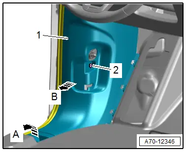
- Unclip the A-pillar gap cover -1- using the -3409- in direction of -arrow A- and disengage at the A-pillar upper trim panel in direction of -arrow B-.
- Unclip the sill panel in the front area from the A-pillar lower trim panel. Refer to → Chapter "Front Sill Panel Strip, Removing and Installing".
Driver Side
- Remove the footrest. Refer to → Chapter "Footrest, Removing and Installing".
- Remove the operating lever handle from the rear lid latch. Refer to → Body Exterior; Rep. Gr.55; Hood; Latch Release Lever, Removing and Installing.
- Remove the bolt -2-.
Continuation for Both Sides of Vehicle
- Free up the A-pillar trim panel near the door seal and disengage at the A-pillar.
- Disengage the A-pillar trim panel -1- at the bottom of the side sill in direction of -arrow A- and pull toward the rear.
- Unclip the A-pillar trim panel from the A-pillar in direction of -arrow B- and remove it.
Installing
Install in reverse order of removal.
Installation notes, for example tightening specifications, replacing components. Refer to → Chapter "Overview - A-Pillar Trim Panel".

