Audi Q7: Pneumatic System, Checking
Preparations, Checking Lumbar Support Air Cushion and Seat Bolster Adjuster for Leaks
 Note
Note
- When an appropriate entry is made in the event memory, there is a prompt in "Guided Fault Finding" to replace the faulty lumbar support air cushion using the -VAS6618/10- using the Vehicle Diagnostic Tester.
- Then the preparations for this leak test are described that must be carried out directly in the seat.
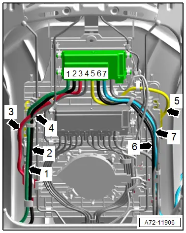
- Connection diagram with assignment of the pneumatic lines to the air cushions. Refer to → Chapter "Connection Diagram - Pneumatic System".
Special tools and workshop equipment required
- Vehicle Diagnostic Tester
- Pneumatic Repair Set -VAS6618A-
Procedure
- The backrest cover must be removed. Refer to → Chapter "Backrest Cover, Removing and Installing".
- Before disconnecting, mark the allocation of the pneumatic lines to each other using a waterproof felt-tip pen.
- Disconnect the pneumatic lines for the faulty lumbar support air cushion each at a distance of 180 mm, measured from the solenoid valve block.
 Note
Note- Wiring connectors applied as an addition may not be opened another time.
- If a pneumatic line at a seat must be disconnected, and a wiring connector was already placed on it at an earlier time, then the new wiring connector must be set 230 mm (9 in.) away from the existing separating point.
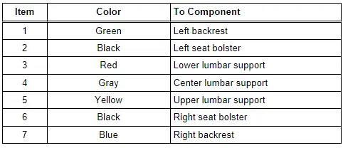
- To connect, attach the connecting sleeves from the -VAS6618- to the pneumatic lines.
 Note
Note- To connect, insert the pneumatic lines in the -VAS6618/2- from both sides in direction of -arrows A-.
- To release, push the release rings in direction of -arrows B- and simultaneously remove pneumatic lines in direction of -C arrows-.
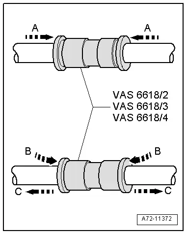
- Connect the -VAS6618/10- on the lines to the lumbar support air cushion.
 Note
Note
The illustration shows the pneumatic line to the lumbar support upper air cushion.
- Connect the pneumatic lines following the leak test. Refer to → Chapter "Pneumatic Lines, Disconnecting and Connecting".
Preparations for Compressor and Pressure Line Leak Check
Special tools and workshop equipment required
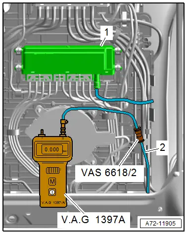
- Turbocharger Tester Kit -VAG1397A-
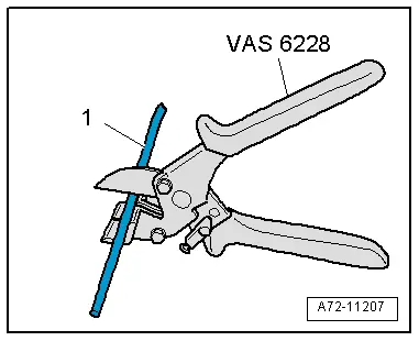
- Hose Cutting Pliers -VAS6228-
- Pneumatic Repair Set -VAS6618A-
- Vehicle Diagnostic Tester
 Note
Note- When an appropriate entry is made in the event memory, there is a prompt in "Guided Fault Finding" to perform a leak check using the Vehicle Diagnostic Tester.
- Then the preparations for this leak test are described that must be carried out directly in the front seat.
- Connection diagram with assignment of the pneumatic lines to the air cushions. Refer to → Chapter "Connection Diagram - Pneumatic System".
Procedure
- The backrest cover must be removed. Refer to → Chapter "Backrest Cover, Removing and Installing".
 Note
Note- To check, the pneumatic line from the compressor is not disconnected at the connection, but is disconnected by the described procedure. Refer to → Chapter "Pneumatic Lines, Disconnecting and Connecting".
- To connect during the leak test, insert the pneumatic lines into the -VAS6618/2- from both sides in direction of -arrows A-.
- To release, push the release rings in direction of -arrows B- and simultaneously remove pneumatic lines in direction of -C arrows-.

In one of the test steps in the "Guided Fault Finding", it instructs to connect the -VAG1397A- at the pneumatic line to the Valve Block 2 in Driver Seat -N476-/ Valve Block 2 in Front Passenger Seat -N478-.
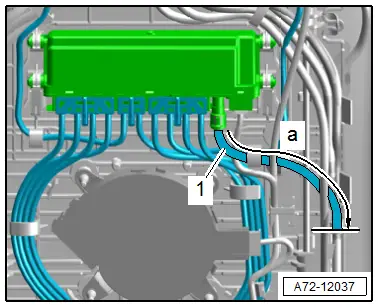
- Disconnect the pneumatic line -1- from the valve block.
a - 120 mm (4.7 in.)
- Using hoses and adapter pieces from the -VAS6618A-, connect the -VAG1397A- to the pneumatic line -2- coming from the compressor.
1 - Valve Block 2 in Driver Seat -N476-/ Valve Block 2 in Front Passenger Seat -N478-
 Note
Note
To connect the pneumatic lines, make an adapter hose from the -VAS6618A-.
- Connect the pneumatic lines following the leak test. Refer to → Chapter "Pneumatic Lines, Disconnecting and Connecting".
Pneumatic Lines, Disconnecting and Connecting
Special tools and workshop equipment required
- Hose Cutting Pliers -VAS6228-
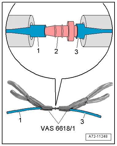
- Pneumatic Repair Set - Pliers -VAS6618/1- (quantity: 2)
Cutting Pneumatic Lines
- Position the -VAS6228- at a right angle and cut the pneumatic line -1-.
Connecting the Pneumatic Line
- Slide the pneumatic lines -1 and 3- onto the line connector -2- on both sides using the -VAS6618/1-. Refer to the Parts Catalog.
- Pull to make sure the pneumatic lines are connected correctly.
Pneumatic Lines, Servicing
- A repair kit with pneumatic lines and line connectors is available for the repair of pneumatic lines. Refer to the Parts Catalog.
- Pneumatic lines must not be disconnected directly at the components, only disconnection and connection according to the methods described below is permissible.
- Original replacement parts are delivered with short sections of line to which pneumatic lines with line connectors are connected.
- Protect pneumatic lines and line connectors from debris.
- Heating the pneumatic lines to connect them to the line connectors is NOT permissible.
- The use of lubricant to connect the pneumatic lines to the line connectors is NOT permissible.
- The repaired pneumatic line is to be exactly as long as the previous line - tolerance +- 10 mm.
- Dirt on the connecting points can cause leaks. Therefore, during tests, make sure the pneumatics and the measuring instruments remain clean.

