Audi Q7: Access/Start Authorization
Component Location Overview - Access/Start Authorization System
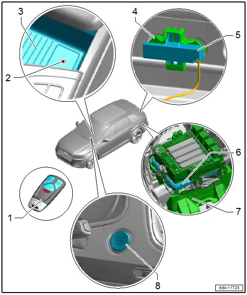
1 - Ignition Key
2 - Access/Start System Antenna 1 in Vehicle Interior -R138-
- With emergency transponder sensor
- Component location overview. Refer to → Chapter "Component Location Overview - Keyless Access Authorization System".
3 - Storage Compartment
- In center console
4 - Bracket
- For access/start system antenna in luggage compartment
5 - Access/Start System Antenna In Luggage Compartment -R137-
- Component location overview. Refer to → Chapter "Component Location Overview - Keyless Access Authorization System".
6 - Comfort System Central Control Module -J393-
- Removing and installing. Refer to → Body Exterior; Rep. Gr.57; Central Locking; Comfort System Central Control ModuleJ393, Removing and Installing.
7 - Mount
- For the comfort system central control module
8 - Access/Start Authorization Button -E408-
- Removing and installing. Refer to → Chapter "Access/Start Authorization Button -E408-, Removing and Installing".
Component Location Overview - Keyless Access Authorization System
Component Location Overview - Front Keyless Access Authorization System
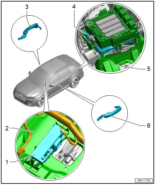
1 - Access/Start System Antenna 1 in Vehicle Interior -R138-
- Removing and installing. Refer to → Chapter "Access/Start System Antenna 1 in Vehicle Interior -R138-, Removing and Installing".
2 - Storage Compartment
- In center console
3 - Front Passenger Side Exterior Door Handle
- With Right Front Exterior Door Handle Touch Sensor -G606-
- Overview. Refer to → Chapter "Overview - Exterior Door Handle for Keyless Access Authorization System".
4 - Comfort System Central Control Module -J393-
- Removing and installing. Refer to → Body Exterior; Rep. Gr.57; Central Locking; Comfort System Central Control ModuleJ393, Removing and Installing.
5 - Bracket
- For the comfort system central control module
6 - Driver Side Exterior Door Handle
- With Left Front Exterior Door Handle Touch Sensor -G605-
- Overview. Refer to → Chapter "Overview - Exterior Door Handle for Keyless Access Authorization System".
Component Location Overview - Rear Keyless Access Authorization System
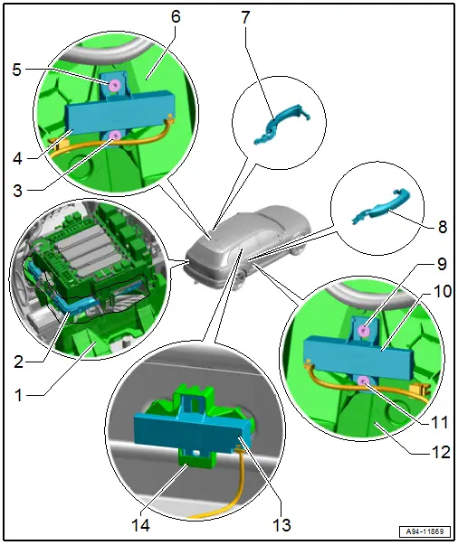
1 - Bracket
- For the comfort system central control module
2 - Comfort System Central Control Module -J393-
- Removing and installing. Refer to → Body Exterior; Rep. Gr.57; Central Locking; Comfort System Central Control ModuleJ393, Removing and Installing.
3 - Bolt
- 1.5 Nm
4 - Left Access/Start Authorization Antenna -R200-
- Removing and installing. Refer to → Chapter "Left and Right Access/Start Authorization Antenna -R200-/-R201-, Removing and Installing".
5 - Bolt
- 1.5 Nm
6 - Door Inner Cover
7 - Rear Driver Side Exterior Door Handle
- With the Left Rear Exterior Door Handle Touch Sensor -G417-
- Overview. Refer to → Chapter "Overview - Exterior Door Handle for Keyless Access Authorization System".
8 - Rear Passenger Side Exterior Door Handle
- With the Right Rear Exterior Door Handle Touch Sensor -G418-
- Overview. Refer to → Chapter "Overview - Exterior Door Handle for Keyless Access Authorization System".
9 - Bolt
- 1.5 Nm
10 - Right Access/Start Authorization Antenna -R201-
- Removing and installing. Refer to → Chapter "Left and Right Access/Start Authorization Antenna -R200-/-R201-, Removing and Installing".
11 - Bolt
- 1.5 Nm
12 - Door Inner Cover
13 - Access/Start System Antenna In Luggage Compartment -R137-
- Removing and installing. Refer to → Chapter "Access/Start System Antenna in Luggage Compartment -R137-, Removing and Installing".
14 - Bracket
- For access/start system antenna in luggage compartment
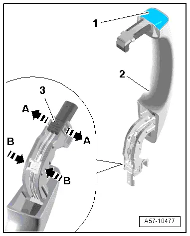
Overview - Exterior Door Handle for Keyless Access Authorization System
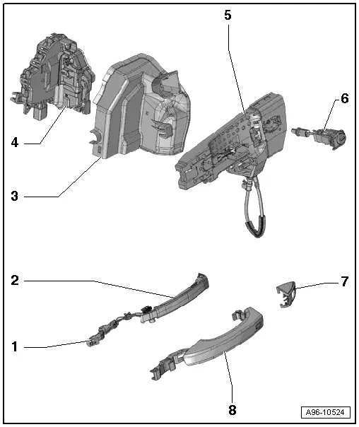
1 - Connector
2 - Left Front Exterior Door Handle Touch Sensor
- In the exterior door handle
Front door:
- Left Front Exterior Door Handle Touch Sensor -G605-, Right Front Exterior Door Handle Touch Sensor -G606-
- Removing and installing. Refer to → Chapter "Front Exterior Door Handle Switch, Removing and Installing".
Rear door:
- Left Rear Outside Door Handle Touch Sensor -G417-, Right Rear Outside Door handle Touch Sensor -G418-
- Removing and installing. Refer to → Chapter "Rear Exterior Door Handle Switch, Removing and Installing".
3 - Anti-Theft Cover
- For the door lock
4 - Door Lock
5 - Mounting Bracket
6 - Lock Cylinder
- Only driver side
7 - Cap
- Driver side for the lock cylinder
- Front passenger side, closed version
8 - Exterior Door Handle
Front Exterior Door Handle Switch, Removing and Installing
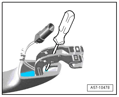
Special tools and workshop equipment required
- T-Handle Hook -3438-
Removing
- Remove the exterior door handle. Refer to → Body Exterior; Rep. Gr.57; Door Components; Door Handle, Removing and Installing.
- Open the tabs in direction of -arrows A- and remove the connector -3-.
- Carefully release the hooks in direction of -arrows B- using a small screwdriver and remove the wiring guide.
1 and 2 - Ignore
- Remove the front exterior door handle illumination bulb, if equipped. Refer to → Chapter "Left and Right Front Exterior Door Handle Illumination Bulb -L162-/-L163-, Removing and Installing".
- Unlock the cover -1- on the exterior door handle -2- using the T-Handle Hook -3438-.
- Remove the cover from the exterior door handle in direction of -arrow-.
- Position a large stabile screwdriver on the exterior door handle as shown.
- Remove the exterior door handle touch sensor toward the front and out of the retainer on the exterior door handle with force.

- Remove the exterior door handle touch sensor from the handle.
Installing
Install in the reverse order of removal while noting the following:
- Slide the exterior door handle touch sensor in until it audibly engages.
Rear Exterior Door Handle Switch, Removing and Installing
Special tools and workshop equipment required
- T-Handle Hook -3438-
Removing
- Remove the exterior door handle. Refer to → Body Exterior; Rep. Gr.58; Door Components; Door Handle, Removing and Installing.
- Open the tabs in direction of -arrows A- and remove the connector -3-.
- Carefully release the hooks in direction of -arrows B- using a small screwdriver and remove the wiring guide.

1 and 2 - Ignore
- Remove the rear exterior door handle illumination bulb, if equipped. Refer to → Chapter "Left and Right Rear Exterior Door Handle Illumination Bulb -L168-/-L169-, Removing and Installing".
- Unlock the cover -1- on the exterior door handle -2- using the T-Handle Hook -3438-.
- Remove the cover from the exterior door handle in direction of -arrow-.
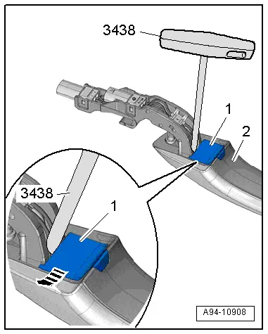
- Position a large stabile screwdriver on the exterior door handle as shown.
- Remove the exterior door handle touch sensor toward the front and out of the retainer on the exterior door handle with force.
- Remove the rear exterior door handle touch sensor from the handle.
Installing
Install in the reverse order of removal while noting the following:
- Slide the rear exterior door handle touch sensor in until it engages audibly.

Access/Start System Antenna 1 in Vehicle Interior -R138-, Removing and Installing
Removing
- Remove the center console. Refer to → Body Interior; Rep. Gr.68; Center Console; Center Console, Removing and Installing.
- Release the locking mechanism in direction of -arrow- and remove the antenna -1- from the mount.
- Disconnect the connector -2-.
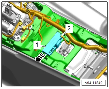
Installing
Install in reverse order of removal.
Access/Start System Antenna in Luggage Compartment -R137-, Removing and Installing
Removing
- Remove the lock carrier trim panel. Refer to → Body Interior; Rep. Gr.70; Luggage Compartment Trim Panels; Lock Carrier Trim Panel, Removing and Installing.
- Release the locking mechanism in direction of -arrow- and remove the antenna -1- from the mount -2-.
- Disconnect the connector -3-.
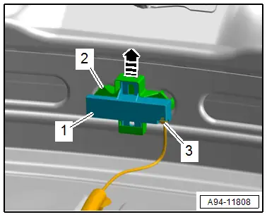
Installing
Install in reverse order of removal.
Left and Right Access/Start Authorization Antenna -R200-/-R201-, Removing and Installing
Removing
- Remove the rear door trim panel. Refer to → Body Interior; Rep. Gr.70; Rear Door Trim Panels; Rear Door Trim Panel, Removing and Installing.
- Remove bolts -arrows- and remove the antenna -1-.
- Disconnect the connector -2-.
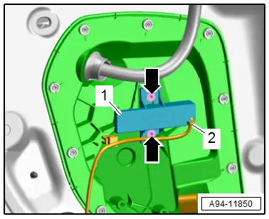
Installing
Install in reverse order of removal.
Tightening Specifications
- Refer to → Chapter "Component Location Overview - Keyless Access Authorization System"

