Audi Q7: Adaptive Cruise Control
Component Location Overview - Adaptive Cruise Control (ACC)
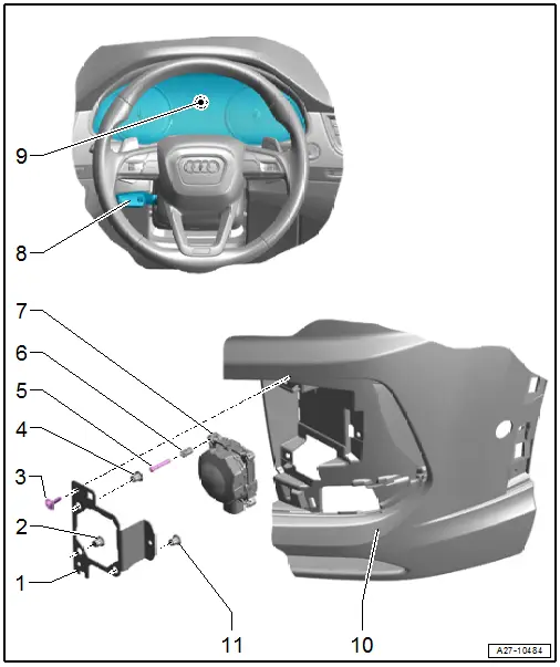
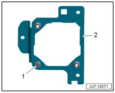
1 - Baseplate
- Removing and installing. Refer to → Chapter "Retaining Plate for Distance Regulation Control Modules -J428-/-J850-, Removing and Installing".
2 - Clip
- Closed version
- Cannot be removed without being damaged
- Note the installation location.
3 - Bolt
- 2.5 Nm
- Quantity: 3
4 - Clip
- Open version
- Cannot be removed without being damaged
5 - Stud Bolt
- Quantity: 3
- Note the adjustment dimension.
6 - Clip
- Quantity: 3
- Must be replaced when the stud bolt is removed
- Replacing. Refer to → Chapter "Distance Regulation Control Module -J428- Clip, Replacing".
7 - Distance Regulation Control Module
- Right: Distance Regulation Control Module -J428-
- Left: Distance Regulation Control Module 2 -J850-
- Removing and installing. Refer to → Chapter "Distance Regulation Control Modules -J428-/-J850-, Removing and Installing".
- Calibrate the adaptive cruise control. Refer to → Suspension, Wheels, Steering; Rep. Gr.44; Adaptive Cruise Control (ACC); Adaptive Cruise Control (ACC), Adjusting.
8 - Operating Lever for Adaptive Cruise Control
- Shared component with the steering column switch module. Cannot be replaced separately
- Removing and installing. Refer to → Chapter "Steering Column Switch Module, Removing and Installing".
9 - Instrument Cluster
- With Instrument Cluster Control Module -J285-
10 - Front Bumper
11 - Clip
- Open version
- Cannot be removed without being damaged
Control Module for Adaptive Cruise Control, Removing and Installing
Distance Regulation Control Modules -J428-/-J850-, Removing and Installing
- If replacing the control module, select the "Replace control module" function for the corresponding control module on the Vehicle Diagnostic Tester.
Removing
- Remove the air intake grille. Refer to → Body Exterior; Rep. Gr.63; Front Bumper; Attachments, Removing and Installing.
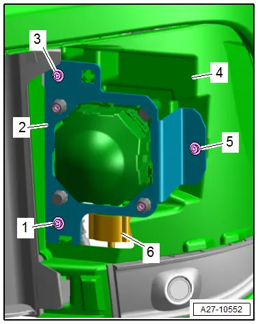
- Remove the bolts -1, 3 and 5-.
- Remove the retaining plate -2- with the distance regulation control module from the baseplate -4-.
- Clean and dry the area around the control module connector.
- Disconnect the connector -6-.
Installing
Install in the reverse order of removal while noting the following:
- Check the connector for damage, contact corrosion and water ingress, and service if necessary. Refer to → Electrical Equipment General Information; Rep. Gr.97; Wiring Harness and Connector Repairs.
- Calibrate the adaptive cruise control (ACC). Refer to → Suspension, Wheels, Steering; Rep. Gr.44; Adaptive Cruise Control (ACC).
Tightening Specifications
- Refer to → Chapter "Component Location Overview - Adaptive Cruise Control (ACC)"
Retaining Plate for Distance Regulation Control Modules -J428-/-J850-, Removing and Installing
Special tools and workshop equipment required
- Digital Caliper -VAS6335-
Removing
- Remove the distance regulation control module. Refer to → Chapter "Distance Regulation Control Modules -J428-/-J850-, Removing and Installing".
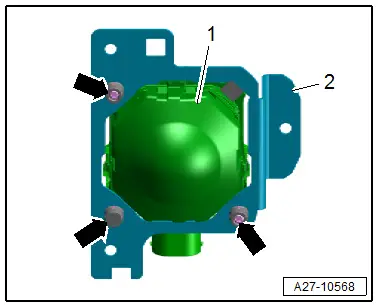
- Place the control module on a soft and clean surface.
- Destroy the clips -arrows-.
- Remove the retaining plate -2- from the Distance Regulation Control Module -J428--1-.
Installing
Install in the reverse order of removal while noting the following:
- Insert the new clips until they engage in the retaining plate.
- Left side of the vehicle: The closed clip -1- must be seated on the bracket -2- below on the inside.
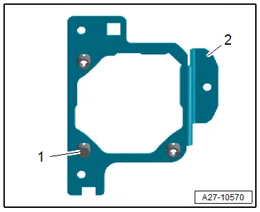
- Right side of the vehicle: The closed clip -1- must be seated on the bracket -2- below on the outside.
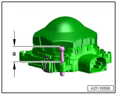
- Measure the dimension -a- at all stud bolts using the Digital Caliper -VAS6335- and correct if necessary.
- Dimension -a- = 17.6 mm.
- Install the retaining plate with the stud bolts on the control module.
- The stud bolt must be aligned correctly to the clip.
- Push the stud bolt -1- all the way in the clip -2- as shown.

Distance Regulation Control Module -J428- Clip, Replacing
The clips cannot be removed without being damaged.
Procedure
- Distance Regulation Control Module -J428- removed from the retaining plate.
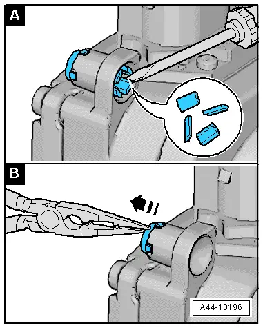
- Place a screwdriver between the hook and the housing.
- Bend every hook all the way around with the screwdriver until it audibly breaks off.
- To prevent the broken hook from getting caught on the housing, remove it from the inside of the clip using needle nose pliers.
- Insert the new clip in the hole in the housing, as shown and push in by hand until it clicks into place.
- The tabs on the clip must sit correctly in the recesses.
- Install the stud bolt.
- The stud bolt must be aligned correctly to the clip.
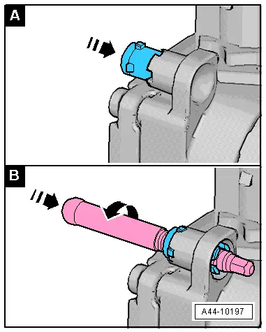
- Turn the stud bolt into the distance regulation control module up to the dimension -a-.
- Measure the dimension -a- at all stud bolts using the Digital Caliper -VAS6335- and correct if necessary.
- Dimension -a- = 17.6 mm.

Special Tools
Special tools and workshop equipment required
- Digital Caliper -VAS6335-

