Audi Q7: Condensation Water Drain, Removing and Installing
Removing
- Turn off the ignition.
- Remove the glove compartment (for the right condensation water drain). Refer to → Body Interior; Rep. Gr.68; Storage Compartments and Covers; Glove Compartment, Removing and Installing.
- Remove the driver side instrument panel cover (for the left condensation water drain). Refer to → Body Interior; Rep. Gr.68; Storage Compartments and Covers; Driver Side Instrument Panel Cover, Removing and Installing.
- Carefully fold back the floor covering near the condensation water drain hose (left or right front at center tunnel) so that the condensation water drain is visible.
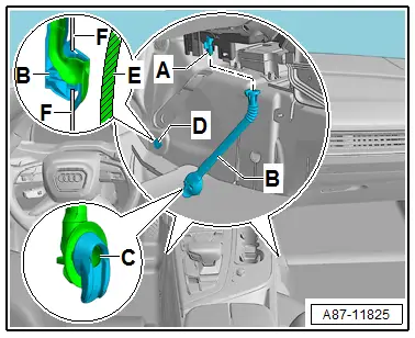
- Check the condensation water drain hoses -B- that they are properly routed and for dirt. Correct, for example, if the hose is constricted.
- Cover the area under both openings -D- (for condensation water drain -C-) with absorbent paper (so that any water present does not get under the carpet).
- Remove both condensation water drain hoses -B- .
- Check both heater and A/C unit condensation water drains -A- for soiling (for example, using a piece of wire).
- Check the gap between the insulation mat installed in the center tunnel -E- and the end of the condensation water hose -C- above the openings -F- in the floor panel -D-; the gap must be large enough so that the condensation water can flow out of the hose -B- .

Installing
Install in reverse order of removal. Note the following:
- Install both condensation water drain hoses -B- so that they are not twisted or crushed (different styles for the left and right side). Refer to the Parts Catalog.
- Insert the condensation water drain -B- and push with pretension in the floor panel -F-.
 Note
Note
The condensation water drain -B- must be pushed with pretension into the floor panel -F- after installing to prevent any condensation water coming out of the drain -B- into the passenger compartment. Seal the area between both parts with silicone adhesive D176 001 A3. Refer to the Parts Catalog.
- Make sure the carpet does not push up against the condensation water drain hose -B- when installing.
- If a condensation water drain hose -B- fits too loose on the heater and A/C unit condensation water drain -A-, secure it with a clamp, for example, so that it cannot slide off.

Condensation Water Drain, Checking
 Note
Note
- This vehicle is equipped with two condensation water drains -B- (left and right on the heater and A/C unit or center tunnel).
- The end -C- of the condensation water drain hose -B- does not have a valve or a door. The condensation water flows out over the rubber seals.
- There are different versions of the condensation water drain hoses -B-. On this version the condensation water drain -B- is inserted in the opening -D-.
For complaints of moisture in passenger compartment, check the following as well as condensation water drain:
- Plenum chamber water drains. Refer to → Chapter "Plenum Chamber Water Drain, Removing and Installing".
- Check the plenum chamber cover and the fresh air intake housing for proper installation and damage. Refer to → Chapter "Fresh Air Intake, Removing and Installing".
- The dust and pollen filter for soiling and correct installation. Refer to → Chapter "Dust and Pollen Filter, Removing and Installing".
- The forced air extraction via the luggage compartment. Refer to → Chapter "Vehicle Interior Forced Air Extraction, Removing and Installing".
- The back pressure door/fresh air door activation and function (refer to → Chapter "Fresh Air Door Motor -V438- Function, Removing and Installing") and air recirculation door (refer to → Chapter "Recirculation Door Motor -V113-, Removing and Installing") for example, via the "output diagnostic test mode" function of the Guided Fault Finding. Refer to Vehicle Diagnostic Tester in the "Guided Fault Finding" function.
- If there are complaints regarding humidity in the passenger compartment which only appears when the A/C compressor is switched on and under certain climatic conditions, check the temperature of the air coming out of the vents from the front heater and A/C unit evaporator as follows. Refer to → Chapter "Localizing Malfunction for Ice Build-Up on Evaporator".
- In the Guided Fault Finding, select the measured value of the Evaporator Vent Temperature Sensor -G263-. Refer to Vehicle Diagnostic Tester in the "Guided Fault Finding" function.
- Check the output temperature of air at evaporator under conditions reported by the customer or at the following setting on the Front A/C Display Control Head -E87-, "Auto" operating mode, A/C compressor switched on (indicator lamp in the A/C or A/C MAX button lights up), temperature setting "Cold", middle fresh air blower speed at a voltage of approximately 7 V on the Fresh Air Blower -V2-, fresh air mode (indicator lamp "Recirculation" button does not light up) and open instrument panel vents, the air vent temperature at the evaporator.
- The sensor measured value is too low (at an ambient temperature above 0 ºC (32 ºF), colder than 0 ºC (32 ºF) for an extended period) or too high (although the A/C system is working properly, greater than 10 ºC (50 ºF), for example). Correct the reason for the deviation while observing the information regarding the cooling output test. Refer to → Chapter "Cooling Output, Checking".