Audi Q7: ATF Circuit
Overview - ATF Circuit
 Caution
Risk of damaging the transmission.
- Remove all the plugs on the ATF lines and on the transmission that were installed during removal.
- The ATF cooling function will not work and the transmission will be damaged if the plugs are forgotten.
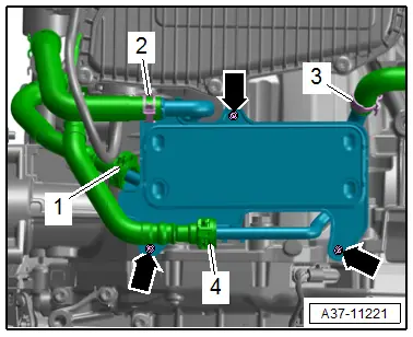
ATF Cooler, ATF Line
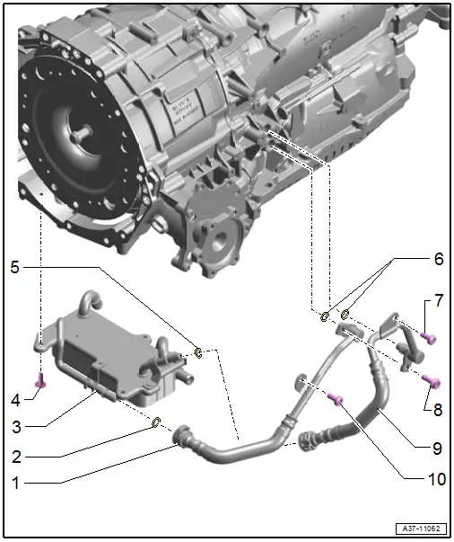
1 - ATF Hose Line
- Cleaning.
- Install all the way by hand with a new O-ring.
2 - O-Ring
- If there are leaks replace the ATF hose line
- Coat with ATF before installing
3 - ATF Cooler
- Removing and installing. Refer to → Chapter "ATF Cooler, Removing and Installing".
4 - Bolt
- 8 Nm
5 - O-Ring
- If there are leaks replace the ATF hose line
- Coat with ATF before installing
6 - O-Rings
- Replacing
- Coat with ATF before installing
7 - Bolt
- 20 Nm
8 - Bolt
- 20 Nm
- First insert the ATF lines with new O-rings by hand as far as the stop
- The retaining tab on the lower ATF line must lie on the transmission threads
- The retaining tab on the upper ATF line must touch the lower one.
9 - ATF Hose Line
- Cleaning.
- Install all the way by hand with a new O-ring.
10 - Bolt
- 20 Nm
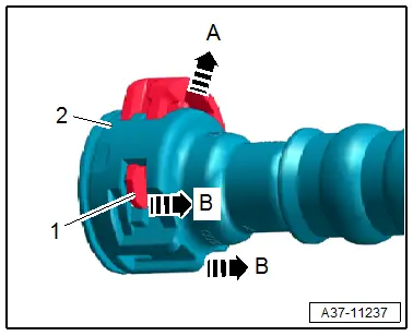
Disconnect the ATF Line
- Release the clip -1- from the connector coupling - 2- in the direction of -B arrows- and lift in the direction of -arrow A-.
- Remove the connector coupling.
Drain and Plug
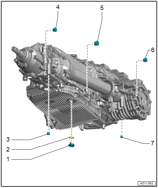
1 - ATF Drain Plug
- Tighten all the way
2 - O-Ring
- Replace after removing
3 - Drain Plug
- 12 Nm
- Replacing
- For the transmission fluid inside the transfer case
4 - Plug
- 27 Nm
- Replacing
- For the hole for checking and filling
- For the transmission fluid inside the transfer case
5 - Plug
- 30 Nm
- Replacing
- For the ATF check and fill hole
6 - Plug
- 27 Nm
- For the hole for checking and filling
- For the transmission fluid inside the front final drive
7 - Drain Plug
- 10 Nm
- For the transmission fluid inside the front final drive
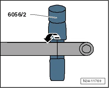
Bleed Pipe Length, Measuring on Oil Filler -VAS6262A- and Shortening if Necessary
The pipe must be shorten to dimension -a- so that the bleed pipe on the adapter for the Oil Filler -VAS6262A- does not touch the bottom on some containers.
- Dimension -a- = 210 mm
 Note
Note
Dimension -a- is measured starting from the shaft (the green surface in the magnified area) on the adapter for the Oil Filler -VAS6262A-.
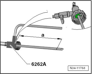
- Mark the dimension on the bleed pipe and shorten it using the Brake Line Tool Kit - Pipe Cutter -VAS6056/2-.
- Clean the Oil Filler -VAS6262A-.
ATF Cooler, Removing and Installing
Special tools and workshop equipment required
- Hose Clamps - Up To 25mm -3094-
- Hose Clip Pliers -VAS6362-
- Used Oil Collection and Extraction Unit -SMN372500-
 Caution
This procedure contains mandatory replaceable parts. Refer to component overview prior to starting procedure.
Mandatory Replacement Parts
- O-rings - ATF lines
Removing
- Remove the subframe crossbrace. Refer to → Suspension, Wheels, Steering; Rep. Gr.40; Subframe; Subframe Crossbrace, Removing and Installing.
 Caution
Risk of damaging the suspension components.
Do not rest the vehicle on its wheels if the subframe mount, the steering gear or the subframe crossbrace are not installed correctly.
- Place the Used Oil Collection and Extraction Unit -SMN372500- under the transmission.
- Disconnect the ATF lines -1 and 4-. Refer to → Fig. "Disconnect the ATF Line".
 Note
Note
Place a clean cloth under the separating point to catch the escaping coolant.
- Loosen the hose clamps -2 and 3- and then disconnect and remove the coolant hoses with Hose Clamps - Up To 25mm -3094-.
- Remove the bolts -arrows- and remove the ATF cooler.
Installing
Install in the reverse order of removal while noting the following:
 Note
Note
Secure all hose connections with hose clamps. Refer to the Parts Catalog.
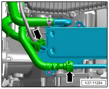
- Connect the ATF line all the way and secure using the clips.
- Loosen all three bolts from the ATF lines -arrows-, but do not remove.
 Caution
The ATF cooler can be damaged by ATF lines installed under stress.
By loosening the bolts tension is created in the ATF lines.
- Re-tighten the bolts -arrows- to the tightening specification.
- Any leaking ATF lines must be replaced.
- Replace bent or stretched clips.
- The clips must be secure.
- Check the ATF level. Refer to → Chapter "ATF Level, Checking".
Tightening Specifications
- Refer to → Chapter "Overview - ATF Circuit".
- Refer to → Suspension, Wheels Steering; Rep. Gr.40; Subframe; Overview - Subframe.
ATF Lines, Removing and Installing
 Caution
This procedure contains mandatory replaceable parts. Refer to component overview prior to starting procedure.
Mandatory Replacement Parts
- O-rings - ATF lines
Special tools and workshop equipment required
- Used Oil Collection and Extraction Unit -SMN372500-
- Hose diameter approximately 18 mm
- Compressed air gun, commercially available
- Protective Eyewear
Removing and Installing
 Note
Note
- General repair instructions. Refer to → Chapter "General Repair Information".
- Guidelines for clean working conditions. Refer to → Chapter "Guidelines for Clean Working Conditions".
- Seal the open lines and connections with clean plugs from the Engine Bung Set -VAS6122-.
- Replace the O-rings after removal.
- Check the ATF level after removing and installing ATF lines. Refer to → Chapter "ATF Level, Checking".
- Remove the center or rear noise insulation. Refer to → Body Exterior; Rep. Gr.66; Noise Insulation; Noise Insulation, Removing and Installing.
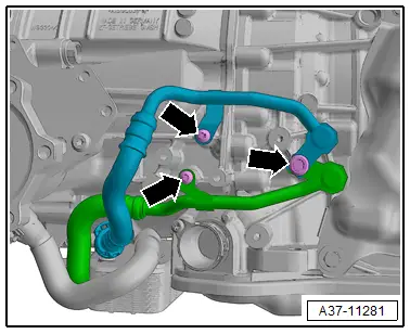
- Disconnect the ATF lines -arrows-. Refer to → Fig. "Disconnect the ATF Line".
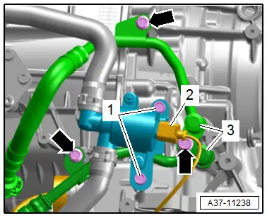
Vehicles with a 3.0L TDI Engine
- Disconnect the connector -3-.
- Remove the bolts -1- and push the Transmission Fluid Cooling Valve -N509- to the side.
All Vehicles
- Remove the bolts -arrows- and remove the ATF lines -2- from the transmission.
 Caution
Risk of damaging the transmission.
- Remove all the plugs on the ATF lines and on the transmission that were installed during removal.
- The ATF cooling function will not work and the transmission will be damaged if the plugs are forgotten.
Clean
 Note
Note
Refer to → Chapter "Guidelines for Clean Working Conditions".
- Before installing a replacement transmission, always clean out the ATF cooler and ATF lines using compressed air (maximum 10 bar (145 psi) ).
- Place the Used Oil Collection and Extraction Unit -SMN372500- under the transmission.
 Note
Note
If extremely dirty ATF flows out when cleaning using compressed air, flush the ATF cooler and lines using clean ATF.
Tightening Specifications
- Refer to → Rep. Gr.19; Coolant Pump/Coolant Thermostat; Overview - Electric Coolant Pump.
- Refer to → Body Exterior; Rep. Gr.66; Noise Insulation; Overview - Noise Insulation.

