Audi Q7: ATF System
Overview - ATF System
 Note
Note
Coat O-rings and seals with ATF. Other types of lubrication leads to faults in the transmission control module hydraulics.
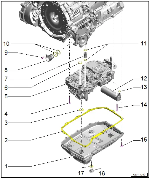
1 - Transmission Fluid Pan
- With integrated ATF filter
- Removing and installing. Refer to → Chapter "Transmission Fluid Pan, Removing and Installing".
2 - Gasket
- Replace after removing
3 - O-Ring
- Replace after removing
4 - Bolt
- Replace after removing
- Tightening specification and sequence. Refer to → Fig. "Mechatronic, Tightening Specification and Sequence".
5 - Mechatronic
- Removing and installing. Refer to → Chapter "Mechatronic, Removing and Installing".
6 - O-Ring
- Replace after removing
7 - ATF Pipe
- Replace after removing
8 - Connector Housing
- Replace after removing
9 - Bolt
- 5.5 Nm
10 - Seals
- Replace together with the connector housing -item 8-.
11 - O-Rings
- Replace together with the ATF line -item 7-.
12 - Hydraulic Pulse Memory with Accumulator Solenoid -N485-
- Removing and installing. Refer to → Chapter "Hydraulic Pulse Memory with Accumulator Solenoid -N485-, Removing and Installing".
13 - O-Ring
- Replacing
- For connecting the hydraulic pulse memory
14 - Bolt
- Replace after removing
- Tightening specification and sequence. Refer to → Fig. "Hydraulic Pulse Memory Tightening Specification and Sequence".
15 - Bolt
- Replace after removing
- Tightening specification and sequence. Refer to → Fig. "Transmission Fluid Pan - Tightening Specification and Sequence".
16 - ATF Drain Plug
- Tighten all the way
17 - O-Ring
- Replace after removing
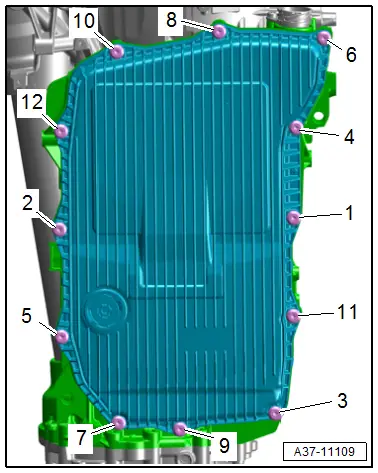
Transmission Fluid Pan - Tightening Specification and Sequence
 Note
Note
- Replace the bolts that were tightened with an additional turn.
- Pay attention to the installation instructions. Refer to → Chapter "Transmission Fluid Pan, Removing and Installing".
- Tighten the bolts in three steps in the sequence shown:

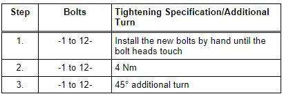
Mechatronic, Tightening Specification and Sequence
- Tighten the bolts to 10 Nm in the following sequence -1 through 18-.
- Install the hydraulic pulse memory -A-. Refer to → Chapter "Hydraulic Pulse Memory with Accumulator Solenoid -N485-, Removing and Installing".
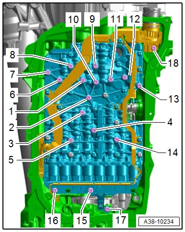
Hydraulic Pulse Memory Tightening Specification and Sequence
 Note
Note
Replace the bolts after removing them.
- Tighten the bolts to 10 Nm in the sequence -1 to 3-.

Hydraulic Pulse Memory with Accumulator Solenoid -N485-, Removing and Installing
 Note
Note
- General repair instructions. Refer to → Chapter "General Repair Information".
- Guidelines for clean working conditions. Refer to → Chapter "Guidelines for Clean Working Conditions".
 Caution
This procedure contains mandatory replaceable parts. Refer to component overview prior to starting procedure.
Mandatory Replacement Parts
- Bolts - Hydraulic pulse memory with accumulator solenoid
- O-ring - Hydraulic pulse memory
Removing
- The transmission is installed.
 Caution
Risk of damaging the transmission.
Do not start the engine if there is no ATF in the transmission and if the Mechatronic is removed.
- Move the transmission into the "P" position.
- Switch the ignition off.
- Remove the ATF oil pan. Refer to → Chapter "Transmission Fluid Pan, Removing and Installing".
 Caution
There is a risk of destroying the transmission control module (Mechatronic) with static discharge.
- Always "discharge" the static electricity before working with connectors. Do this by touching a grounded object, for example vehicle ground, the vehicle or the hoist.
- Do not touch connector terminals in the transmission connector with hands.
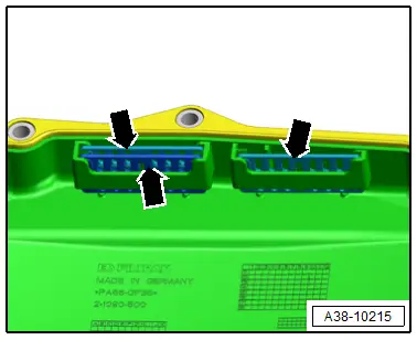
- Disconnect the connector -B- for the hydraulic pulse memory -A- carefully.
- Remove the bolts in the sequence -3 to 1-.
- Remove the hydraulic pulse memory.
Installing
 Note
Note
Replace the O-ring and bolts for the hydraulic pulse memory.
- Install the hydraulic pulse memory -A- with a new O-ring -D-.
- Tighten the bolt in the following sequence: -1 to 3-.
- Disconnect the connector -B- for the hydraulic pulse memory carefully.
 Note
Note
Make sure the connector locks and is secure.
- Route the wire -C- according to the illustration and secure it -arrows-.
- Install the ATF pan. Refer to → Chapter "Transmission Fluid Pan, Removing and Installing".
- Fill with ATF. Refer to → Chapter "ATF Level, Checking".

Tightening Specifications
- Refer to → Chapter "Overview - ATF System"
Transmission Fluid Pan, Removing and Installing
 Caution
This procedure contains mandatory replaceable parts. Refer to component overview prior to starting procedure.
Mandatory Replacement Parts
- Bolts - ATF
- Gasket - ATF pan
Removing
 Note
Note
- General repair instructions. Refer to → Chapter "General Repair Information".
- Guidelines for clean working conditions. Refer to → Chapter "Guidelines for Clean Working Conditions".
- Remove the subframe crossbrace. Refer to → Suspension, Wheels, Steering; Rep. Gr.40; Subframe; Subframe Crossbrace, Removing and Installing.
 Caution
Risk of damaging the suspension components.
Do not rest the vehicle on its wheels if the subframe mount, the steering gear or the subframe crossbrace are not installed correctly.
- Remove the transmission support with the transmission mount. Refer to → Rep. Gr.10; Subframe Mount; Transmission Mount, Removing and Installing.
- Drain the ATF. Refer to → Chapter "ATF, Draining and Filling".
- Free up the wires.
- Remove the bolts from the ATF pan in the sequence -12 through 1-.
- Remove the ATF oil pan.

Installing
Install in the reverse order of removal while noting the following:
 Note
Note
When installing use the complete repair kit.
- Clean the magnets -arrows-.
- Thoroughly clean the sealing surface.
- Install the bolts -1 and 2- by hand until the bolt heads make contact.
- Tighten the bolts in the specified tightening sequence.
- Fill with ATF. Refer to → Chapter "ATF, Draining and Filling".
Tightening Specifications
- Refer to → Fig. "Transmission Fluid Pan - Tightening Specification and Sequence"
- Refer to → Rep. Gr.10; Subframe Mount; Overview - Subframe Mount.
- Refer to → Suspension, Wheels Steering; Rep. Gr.40; Subframe; Overview - Subframe.

