Audi Q7: Mechatronic
Mechatronic, Removing and Installing
Special tools and workshop equipment required
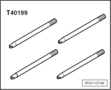
- Oil Sump Assembly Pin -T40199-
 Caution
This procedure contains mandatory replaceable parts. Refer to component overview prior to starting procedure.
Mandatory Replacement Parts
- Bolts - Mechatronic
- O-rings - ATF pipe
- O-ring - Mechatronic
- Seals - Connector housing
Removing
- The transmission is installed.
 Note
Note
- General repair instructions. Refer to → Chapter "General Repair Information".
- Guidelines for clean working conditions. Refer to → Chapter "Guidelines for Clean Working Conditions".
- Always replace the Mechatronic unit if it is dirty or defective.
 Caution
Risk of damaging the transmission.
Do not start the engine if there is no ATF in the transmission and if the Mechatronic is removed.
- Move the transmission into the "P" position.
- Switch the ignition off.
- Remove the ATF oil pan. Refer to → Chapter "Transmission Fluid Pan, Removing and Installing".
 Caution
There is a risk of destroying the transmission control module (Mechatronic) with static discharge.
- Always "discharge" the static electricity before working with connectors. Do this by touching a grounded object, for example vehicle ground, the vehicle or the hoist.
- Do not touch connector terminals in the transmission connector with hands.
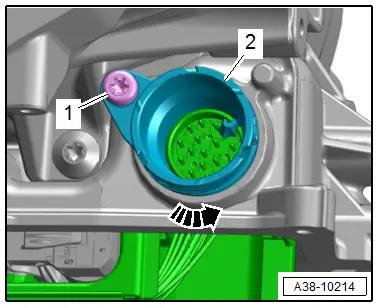
- Turn the twist lock counter-clockwise -arrow- and disconnect the connector from the transmission.

- Remove the bolt -1-.
- Turn the connector housing -2- counter-clockwise -arrow- and remove it.

 Note
Note
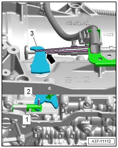
- For better accessibility position the selector lever -3- for the parking lock emergency release in vertical position and secure it in this position with a cable tie -arrow-. The selector slide -1- can then engage easier into the claw -2- of the emergency release during installation.
- The installation position on a vehicle with 3.0L TFSI engine is shown.

 Caution
Risk of causing damage to the Mechatronic.
- Only the bolts with a T40 TORX bolt head may be loosened.
- If other bolts are loosened, this may impair the function of the Mechatronic unit or it may come apart.
- Remove the hydraulic pulse memory. Refer to → Chapter "Hydraulic Pulse Memory with Accumulator Solenoid -N485-, Removing and Installing".
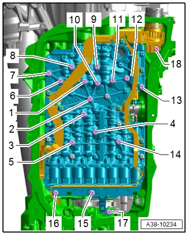
- Remove the bolts in the sequence -18 to 2-.
 Note
Note
Do not remove the bolt -1- yet.
- Install the four Oil Sump Assembly Pin -T40199- in the threaded holes -5, 7, 12 and 14- hand-tight.
- Remove the bolt -1-.
- Remove the Mechatronic.
 Caution
Danger of damaging the sensor on the back side of the Mechatronic.
Lay the Mechatronic with the bolt head side facing down only.
Installing
 Note
Note
When installing use the complete repair kit.
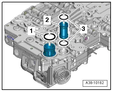
- Install new O-rings -1 and 3- into the grooves in the oil pipes.
- Install the ATF line -2- into the Mechatronic.
- Check the oil pipes for damage and make sure they fit securely inside the Mechatronic.
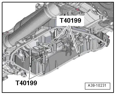
- If still not present, install the four Oil Sump Assembly Pin -T40199- hand-tight, as shown.
 Note
Note
- The Oil Sump Assembly Pin -T40199- prevent the Mechatronic from tilting when it is being installed. Also, the oil pipes on the back of the Mechatronic will not get damaged.
- The spring clip on the back of the Mechatronic prevents the Mechatronic from being mounted flush on the transmission housing.
- It is recommended to have a second technician help when installing the Mechatronic.
- Secure the gearshift lever -3- in a vertical position using a cable tie -arrows-.
- Mount the Mechatronic on the transmission housing.
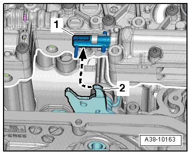
- The claw -2- on the emergency release must fit behind the pin in the selector slider -1--arrow-.
- Install the bolts -1 through 4- by hand until the bolt heads make contact.
- Remove the four Oil Sump Assembly Pin -T40199-.
- Tighten the bolts on the Mechatronic in the specified tightening sequence. Refer to → Fig. "Mechatronic, Tightening Specification and Sequence".
- Install the hydraulic pulse memory. Refer to → Chapter "Hydraulic Pulse Memory with Accumulator Solenoid -N485-, Removing and Installing".

Further installation is performed in reverse order of removal. Note the following:
 Caution
There is a risk of destroying the transmission control module (Mechatronic) with static discharge.
- Always "discharge" the static electricity before working with connectors. Do this by touching a grounded object, for example vehicle ground, the vehicle or the hoist.
- Do not touch connector terminals in the transmission connector with hands.
- Install the new connector housing -2- with the tab downward and then turn it opposite the direction of the -arrow-.
- Make sure the connector locks and is secure.
- Tighten the bolt -1-.
- Remove the cable tie -arrow-.
- Install the ATF pan. Refer to → Chapter "Transmission Fluid Pan, Removing and Installing".
- Connections and routing. Refer to → Wiring diagrams, Troubleshooting & Component locations.
- Fill with ATF. Refer to → Chapter "ATF Level, Checking".

Tightening Specifications
- Refer to → Chapter "Overview - ATF System"
Special Tools
Special tools and workshop equipment required
- Oil Sump Assembly Pin -T40199-