Audi Q7: Camshaft, Measuring Axial Clearance
Special tools and workshop equipment required
- Dial Gauge Holder -VW387-
- Dial Gauge - 0-3mm -VAS6080-
Procedure
- Remove the camshafts. Refer to → Chapter "Camshaft, Removing and Installing".
- Mark the allocation of the roller rocker lever for installation later.
- Remove the roller rocker lever and place it on a clean surface.
- Reinstall the camshafts and the guide frame. Refer to → Fig. "Guide Frame for the Camshaft Cylinder Head Bank 1 (Right) - Tightening Specification and Sequence" or → Fig. "Guide Frame for the Camshaft Cylinder Head Bank 2 (Left) - Tightening Specification and Sequence" and tighten the old bolts to 8 Nm without an additional turn.
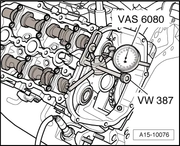
- Secure the Dial Gauge Holder -VW387- with the Dial Gauge - 0-10mm -VAS6079- on the cylinder head as shown.
- Press the camshaft against the dial gauge by hand.
- Set the dial gauge to "0".
- Press the camshaft off of the dial gauge and read the value.
- Axial play: 0.100 to 0.191 mm.
Camshaft, Measuring Radial Clearance
Special tools and workshop equipment required
- Plastigage
Procedure
![]() Note
Note
Use old bolts to measure radial clearance measurement.
- Remove the camshafts. Refer to → Chapter "Camshaft, Removing and Installing".
- Mark the allocation of the roller rocker lever for installation later.
- Remove the roller rocker lever and place it on a clean surface.
- Clean the bearing and the bearing journals.
- Place the Plastigage over entire width of bearing journal or into the bearing.
- The Plastigage must rest in center of bearing.
- Install the camshafts, mount the guide frame and tighten the old bolts. Refer to → Fig. "Guide Frame for the Camshaft Cylinder Head Bank 1 (Right) - Tightening Specification and Sequence" or → Fig. "Guide Frame for the Camshaft Cylinder Head Bank 2 (Left) - Tightening Specification and Sequence". When doing this, be careful not to rotate the camshafts.
- Remove the bearing bracket and camshafts.
- Compare the width of the Plastigage with the measuring scale.
Radial clearance:
- For 24 mm bearing diameter: 0.024 to 0.066 mm
- For 36 mm bearing diameter: 0.032 to 0.078 mm
- Replace the bolts for the final assembly.
Camshaft, Removing and Installing
Special tools and workshop equipment required
- Impact Puller -T10133/3- from Injector/Combustion Chamber Seal Tool Set -T10133C-
- Locating Pins -T40116-
- Hand Drill with Plastic Brush Attachment
- Protective Eyewear
- Sealant. Refer to the Parts Catalog.
![]() Caution
Caution
This procedure contains mandatory replaceable parts. Refer to component overview prior to starting procedure.
Mandatory Replacement Parts
- Bolts - Guide frame(s)
- O-ring - Camshaft adjustment valve(s)
Removing
- Remove the camshaft timing chains from the camshafts. Refer to → Chapter "Camshaft Timing Chain, Removing from Camshafts".
Cylinder Bank 1 (Right):
- Remove the high pressure pump. Refer to → Chapter "High Pressure Pump, Removing and Installing".
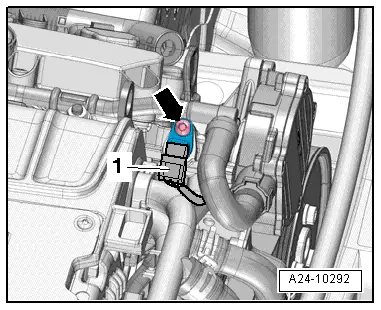
- Disconnect the connector -2- on the Camshaft Position Sensor -G40-.
- Remove the bolts -arrows- and the high pressure pump housing -1-.
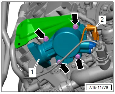
- Remove the bolt -arrow- for the ground wire.
- Move the electrical wiring harness to the side.
Cylinder Bank 2 (Left):
- Remove the vacuum pump. Refer to → Brake System; Rep. Gr.47; Vacuum System; Vacuum Pump, Removing and Installing.
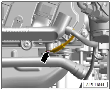
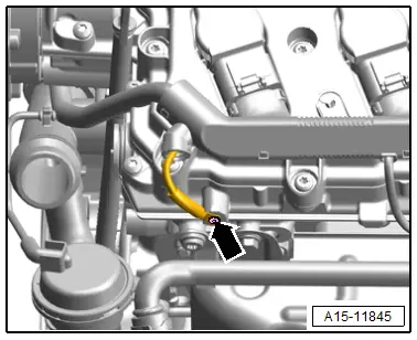
- Disconnect the connector -1- for the Camshaft Position Sensor 2 -G163-.
![]() Note
Note
Ignore the -arrow-.
- Remove the bolt -arrow- for the ground wire.
- Move the electrical wiring harness to the side.
Continuation for Both Sides:
- Remove the respective intake manifold lower section. Refer to → Chapter "Intake Manifold Lower Section with Fuel Rail, Removing and Installing".
- Remove the bolts -arrows- and the corresponding camshaft adjuster valves.
Cylinder Bank 1 (Right):
![]() Note
Note
For better accessibility loosen the high pressure line on the fuel rail and on the bracket. Leave the high pressure line in the installation position.
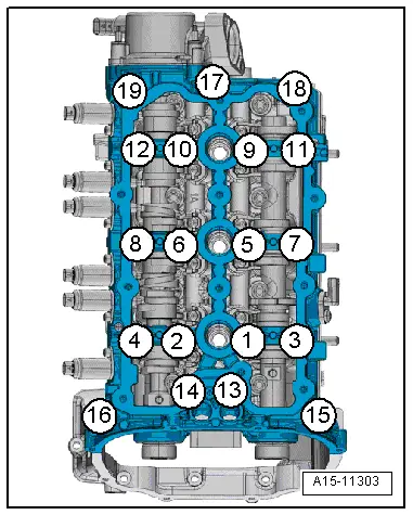
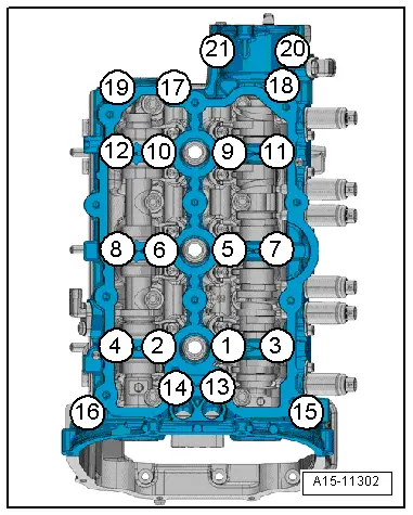
- Loosen the guide frame bolts in the following sequence: -19 to 1-.
- Remove the bolts, carefully loosen the guide from out of the bond and place it with the camshafts on a soft surface.
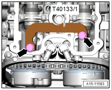
- Remove the Camshaft Clamp -T40133/1--arrows-.
- Mark the camshafts, remove them and lay them on a clean surface.
Cylinder Bank 2 (Left):
- Loosen the guide frame bolts in the following sequence: -21 through 1-.
- Remove the bolts, carefully loosen the guide from out of the bond and place it with the camshafts on a soft surface.
- Remove the Camshaft Clamp -T40133/2--arrows-.

Installing
![]() Note
Note
Replace the seals and plugs after removal.
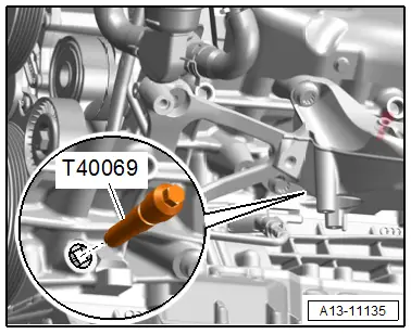
- Secure crankshaft in "TDC" position using Crankshaft Locking Pin -T40069-.
- The hydraulic lifters and roller rocker lever are inserted.
![]() Caution
Caution
Risk of contaminating the lubricating system and the bearing.
Cover open engine components.
![]() WARNING
WARNING
Risk of eye injury.
Wear protective eyewear!
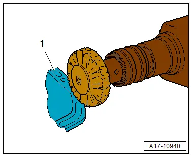
- Remove any sealant residue on the cylinder head and the guide frame -1- using a rotating plastic brush.
- Clean any oil or grease off the sealing surfaces.
- Oil the camshaft running surfaces.
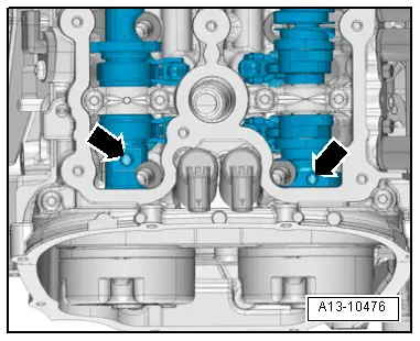
- Insert the camshafts in the guide frame.
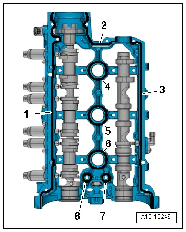
- The placement of the camshafts must be exactly within the axial bearings -arrows- of the guide frame.
- The compression ring ends -1, 2 and 3- must face up or down. They must never face sideways.
![]() Note
Note
Depending on the version on the exhaust camshaft one or two compression rings -2 or 3- are installed. Refer to the Parts Catalog for the allocation.
- Rotate the guide frame with the camshafts inserted while holding them securely in the frame.
- Rotate the camshafts until the threaded holes -arrows- face upward.
- Check if the camshafts still lie in the guide frame axial bearings.
Cylinder Bank 1 (Right):
- Install the Camshaft Clamp -T40133- on cylinder head -arrows- and tighten to 25 Nm.

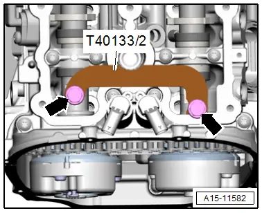
Cylinder Bank 2 (Left):
- Install the Camshaft Clamp 2 -T40133/2- on cylinder head -arrows- and tighten to 25 Nm.
Continuation for Both Cylinder Banks:
![]() Note
Note
Note the expiration date for the sealant.
- Cut the tube nozzle at the front marking (nozzle diameter: about 2 mm).
- Rotate the guide frame again.
![]() Caution
Caution
Risk of contaminating camshaft bearing with excess sealant.
Do not apply sealant beads thicker than indicated.
- Apply sealant beads -4 through 8- to the clean sealing surfaces on the guide frame as shown in the illustration.
- Sealant bead thickness, 2.0 mm.
- Apply sealant beads -1 through 3- to the clean sealing surfaces on the guide frame as shown in the illustration.
- Sealant bead thickness: 2.5 mm.
![]() Note
Note
The guide frame must be installed within five minutes after applying the sealant.
- Place the guide frame on the cylinder head.
- Install the Locating Pins -T40116- into the guide frame and cylinder head.
- Tighten the camshaft guide frame bolts.
![]() Note
Note
After installing the guide frame, let the sealant harden for approximately 30 minutes.
- Clean the external sealing head holes in the left and right cylinder heads of oil and grease.
- Coat the outer edge of the sealing plug -arrow- with sealant. Refer to Parts Catalog.
- Drive in the sealing plugs until they are flush.
- Remove the Locating Pins -T40116- with the Injector/Combustion Chamber Seal Tool Set - Impact Puller -T10133/3-.
Installation is performed in reverse order of removal, while noting the following:
- Install the camshaft adjustment valves. Refer to → Chapter "Overview - Cylinder Head".
- Install the intake manifold lower section. Refer to → Chapter "Intake Manifold Lower Section with Fuel Rail, Removing and Installing".
- Install the high pressure pump motor housing and the high pressure pump. Refer to → Chapter "High Pressure Pump, Removing and Installing".
- Install the vacuum pump. Refer to → Brake System; Rep. Gr.47; Vacuum System; Vacuum Pump, Removing and Installing.
- Connections and wire routing. Refer to → Wiring diagrams, Troubleshooting & Component locations.
- Position the camshaft timing chains on the camshafts. Refer to → Chapter "Camshaft Timing Chain, Removing and Installing".
![]() Caution
Caution
Risk of damaging the valves and piston crowns after working on valvetrain.
- The motor must not be started for about 30 minutes after installing camshafts because the hydraulic lifters must seat themselves.
- To ensure valves do not strike pistons when starting, carefully rotate the engine at least two full revolutions.
Tightening Specifications
- Refer to → Chapter "Overview - Valvetrain"
- Refer to → Fig. "Guide Frame for the Camshaft Cylinder Head Bank 1 (Right) - Tightening Specification and Sequence"
- Refer to → Fig. "Guide Frame for the Camshaft Cylinder Head Bank 2 (Left) - Tightening Specification and Sequence"
Camshaft Adjuster Valves, Removing and Installing
![]() Caution
Caution
This procedure contains mandatory replaceable parts. Refer to component overview prior to starting procedure.
Mandatory Replacement Parts
- O-ring - Camshaft adjuster valve(s)
Removing
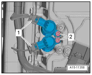
- Disconnect the connector -1-.
- Remove the bolt -2- in question and then remove the valve:
Installing
Install in reverse order of removal and note the following:
![]() Note
Note
- Replace the O-rings after removing them.
- Secure all hose connections with hose clamps that match the ones used in series production. Refer to the Parts Catalog.
Tightening Specifications
- Refer to → Chapter "Overview - Valvetrain"
Hydraulic Lifter, Checking
![]() Note
Note
- The hydraulic lifter cannot be repaired.
- Irregular valve noises are normal while starting the engine.
Special tools and workshop equipment required
- Crankshaft Socket -T40058-
- Feeler Gauge
Procedure
- Start the engine and let it run until the radiator fan switches on once.
- Increase the engine speed for about two minutes to approximately 2500 RPM. Perform a road test if necessary.
- If the hydraulic lifters are still loud, determine which lifter is faulty as follows:
- Remove the cylinder head cover. Refer to → Chapter "Cylinder Head Cover, Removing and Installing".
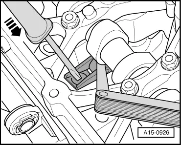
- Rotate the crankshaft in direction of engine rotation in direction of -arrow- using the Crankshaft Socket -T40058- and offset open-end wrench.
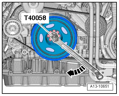
- To determine the play between cam lobes and roller rocker lever, press the lever down in direction of -arrow-.
- If a 0.20 mm feeler gauge can slide between the cam lobes and roller rocker lever, replace the hydraulic lifter. Refer to → Chapter "Camshaft, Removing and Installing".
Final Procedures
- Install the cylinder head cover. Refer to → Chapter "Cylinder Head Cover, Removing and Installing".