Audi Q7: Valve Stem Seals, Removing and Installing
Valve Stem Seals, Removing and Installing, Cylinder Head Installed
Special tools and workshop equipment required
- Spark Plug Removal Tool -3122B-
- Puller - Valve Seal -3364-
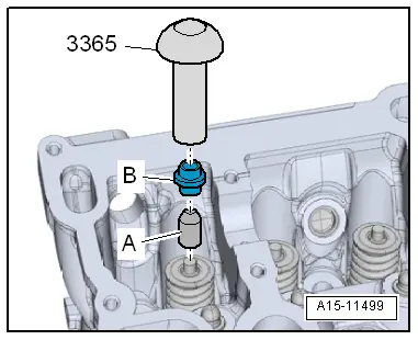
- Seal Installer - Valve Stem -3365-
- Valve Keeper Tool Kit -VAS5161A- with the Valve Cotter Tool Kit - Guide Plate 19c -VAS5161/19C-
- Valve Cotter Tool Kit - Adapter -T40012-
Procedure
- Remove the camshafts. Refer to → Chapter "Camshaft, Removing and Installing".
- Mark the allocation of the roller rocker lever and the hydraulic lifter so they can be installed again.
- Remove the roller rocker levers with the hydraulic lifter and place them on a clean surface.
- Remove the spark plugs with Spark Plug Removal Tool -3122B-.
- Set the piston for the respective cylinder to "bottom dead center (BDC)".
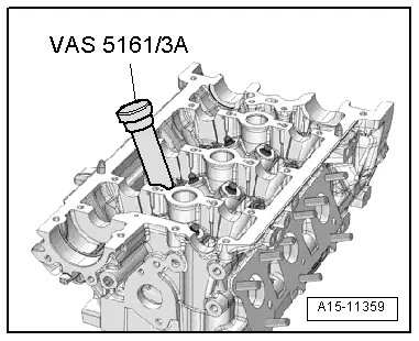
- Position the Valve Cotter Tool Kit - Punch -VAS5161/3A- on the valve spring plate and loosen the stuck valve retainers with a plastic mallet.

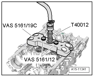
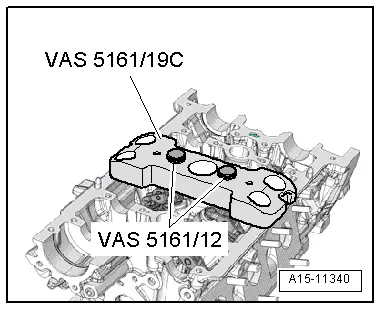
- Place Valve Cotter Tool Kit - Guide Plate -VAS5161/19C- from Valve Cotter Tool Kit -VAS5161A- on the cylinder head.
- Secure the guide plate with the Valve Cotter Tool Kit - Knurled Thumb Screws -VAS5161/12-.
- Install the Valve Cotter Tool Kit - Adapter -T40012/1- with sealing ring in the spark plug thread and tighten by hand.
- Connect the adapter to the compressed air using a commercially available intermediate piece and give steady pressure.
- Minimum pressure, 6 bar (87.02 psi).
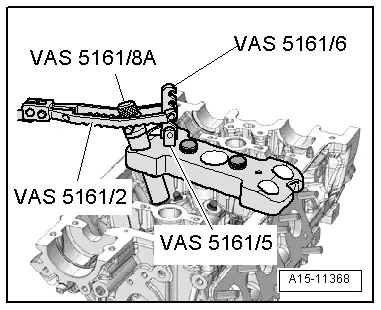
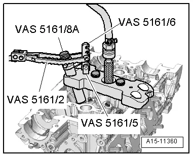
- Install the Valve Cotter Tool Kit - Retainer -VAS5161/6- with the Valve Cotter Tool Kit - Guide Forks M6/M8 Threaded -VAS5161/5- in the guide plate.
- Push the Valve Cotter Tool Kit - Assembly Cartridge -VAS5161/8A- into the guide plate.
- Engage the Valve Keeper Tool Kit - Pressure Fork -VAS5161/2- at the engaging device and press the installation cartridge downward.
- At the same time, turn the installation cartridge knurled bolt right until points engage in the valve retainers.
- Move the knurled bolt left and right slightly. This presses the valve retainers apart and captures them in the assembly cartridge.
- Release the pressure fork.
- Remove the cartridge.
- Remove the guide plate and turn it aside.
- The pressurized air hose remains connected.
- Remove the valve spring and the valve spring retainer.

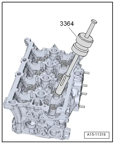
- Remove the valve stem seal with the Puller - Valve Seal -3364-.

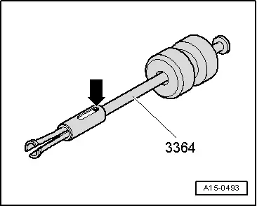
If the Puller - Valve Seal -3364- cannot be used on some valve stem seals due to restricted clearance, proceed as follows.
- Drive out the tensioning pin -arrow- on the puller with a drift and remove the impact puller attachment.
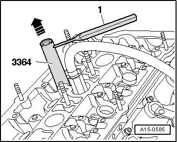
- Position the lower section of the Puller - Valve Seal -3364- on the valve stem seal.
- Secure the puller with a drift or cotter pin drive -1- as shown in the illustration.
- Position the extractor lever on the puller and remove the valve stem seal in direction of -arrow-.
 Caution
There is a risk of damage when installing valve stem seals.
Place the plastic sleeve -A- that is included with the new valve stem seals -B- on the valve stem.
- Lightly oil the valve stem seal sealing lip.
- Slide the valve stem seal onto the plastic sleeve.
- Carefully press the valve stem seal onto the valve guide with the Seal Installer - Valve Stem -3365-.
- Remove the plastic sleeve again.
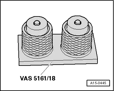
If the valve retainers were removed from the installation cartridge, they must be inserted into the Valve Cotter Tool Kit - Valve Insertion Device -VAS5161/18- first.
- The large diameter of the valve retainers point upward.
- Press the installation cartridge from above onto valve retainer inserting tool and valve retainers.
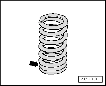
- Insert the valve spring and the valve spring retainer.
- The tight spring coils -arrow- face toward cylinder head.

- Attach the Valve Cotter Tool Kit - Guide Plate 19c -VAS5161/19C- onto the cylinder head again.
- Insert the installation cartridge into the guide plate.
- Press the pressure fork down and pull the knurled bolt up while turning left and right. This inserts the valve retainers.
- Release the pressure fork with the knurled bolt still raised.
- Repeat the procedure on each valve.
Assembling
- Make sure all the roller rocker levers lie on the ends of the valve stems correctly and are clipped onto the respective hydraulic lifters.
- Install the spark plugs.
- Install the camshafts. Refer to → Chapter "Camshaft, Removing and Installing".
 Caution
Risk of damaging the valves and piston crowns after working on valvetrain.
- The motor must not be started for about 30 minutes after installing camshafts because the hydraulic lifters must seat themselves.
- To ensure valves do not strike pistons when starting, carefully rotate the engine at least two full revolutions.
Valve Stem Seals, Removing and Installing, Cylinder Head Removed
Special tools and workshop equipment required
- Puller - Valve Seal -3364-
- Seal Installer - Valve Stem -3365-
- Valve Keeper Tool Kit -VAS5161A- with the Valve Cotter Tool Kit - Guide Plate 19c -VAS5161/19C-
- Engine and Gearbox Bracket -VAS6095A-
- Cylinder Head Tensioning Device -VAS6419-
Procedure
- Remove the camshafts. Refer to → Chapter "Camshaft, Removing and Installing".
- Mark the allocation of the roller rocker lever and the hydraulic lifter so they can be installed again.
- Remove the roller rocker levers with the hydraulic lifter and place them on a clean surface.
- Insert the Cylinder Head Tensioning Device -VAS6419- in the Engine and Gearbox Bracket VAS6095A -VAS6095A-.
- Tension the cylinder head on the cylinder head tensioning device, as shown.
- Connect the cylinder head tensioning device to compressed air.
- Slide the air cushion with the lever -arrow- under the combustion chamber onto the valve stem seal that will be removed.
- Let enough compressed air flow into the air cushion until it contacts the valve plate.
- Position the Valve Cotter Tool Kit - Punch -VAS5161/3A- on the valve spring plate and loosen the stuck valve retainers with a plastic mallet.
- Place the Valve Cotter Tool Kit - Guide Plate 19C -VAS5161/19C- on the cylinder head.
- Secure the guide plate with the Valve Cotter Tool Kit - Knurled Thumb Screws -VAS5161/12-.
- Install the Valve Cotter Tool Kit - Retainer -VAS5161/6- with the Guide Forks M6/M8 Threaded -VAS5161/5- in the guide plate.
- Push the Valve Cotter Tool Kit - Assembly Cartridge -VAS5161/8A- into the guide plate.
- Engage the Valve Keeper Tool Kit - Pressure Fork -VAS5161/2- at the engaging device and press the installation cartridge downward.
- At the same time, turn the installation cartridge knurled bolt right until points engage in the valve retainers.
- Move the knurled thumb screw back and forth slightly. This presses the valve retainers apart and captures them in the installation cartridge.
- Release the pressure fork.
- Remove the cartridge.
- Remove the guide plate and turn it aside.
- Remove the valve spring and the valve spring retainer.

- Remove the valve stem seal with the Puller - Valve Seal -3364-.
 Caution
There is a risk of damage when installing valve stem seals.
Place the plastic sleeve -A- that is included with the new valve stem seals -B- on the valve stem.
- Lightly oil the valve stem seal sealing lip.
- Slide the valve stem seal onto the plastic sleeve.
- Carefully press the valve stem seal onto the valve guide with the Seal Installer - Valve Stem -3365-.
- Remove the plastic sleeve again.

If the valve retainers were removed from the installation cartridge, they must be inserted into the Valve Cotter Tool Kit - Valve Insertion Device -VAS5161/18- first.
- The large diameter of the valve retainers point upward.
- Press the installation cartridge from above onto valve retainer inserting tool and valve retainers.

- Insert the valve spring and the valve spring retainer.
- The tight spring coils -arrow- face toward cylinder head.
- Attach the Valve Cotter Tool Kit - Guide Plate 19c -VAS5161/19C- onto the cylinder head again.
- Insert the installation cartridge into the guide plate.
- Press the pressure fork down and pull the knurled bolt up while turning left and right. This inserts the valve retainers.
- Release the pressure fork with the knurled bolt still raised.
- Repeat the procedure on each valve.
Assembling
Assemble in the reverse order of removal. Note the following:
- Make sure all the roller rocker levers lie on the ends of the valve stems correctly and are clipped onto the respective hydraulic lifters.
- Install the camshafts. Refer to → Chapter "Camshaft, Removing and Installing".