Audi Q7: Drive Axle
Overview - Drive Axle
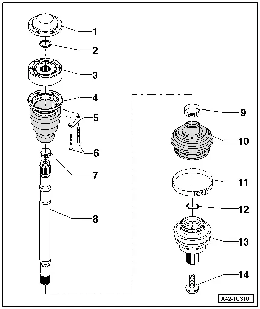
1 - Cover
- Carefully drive off using a drift
- Replace if damaged
- Adhesive surface must be free of oil and grease
- Coat the sealing surface with Sealant -D 454 300 A2- before installing on CV joint.
2 - Circlip
- Replace after removing
- Insert in shaft groove
3 - Inner CV Joint
- Only replace completely
- Checking. Refer to → Chapter "Inner CV Joint, Checking".
- Grease quantity and type.
- The adhesive surfaces must be free of oil and grease
- When installing the CV joint thinly coat the profile shaft splines with the grease used in the joint.
4 - CV Boot
- Without vent hole
- Remove carefully using a drift.
- Check for tears and scuffing
- Check the inner CV joint if damaged. Refer to → Chapter "Inner CV Joint, Checking".
- The metal cap/CV joint sealing surfaces must be free of grease when installing.
5 - Backing Plate
6 - Bolts
- 70 Nm
- Replace after removing
7 - Clamp
- Replace after removing
- Tensioning. Refer to → Fig. "Tension the clamp using the Clampling Pliers -VAG1682A-.".
8 - Drive Axle
- Removing and installing. Refer to → Chapter "Drive Axle, Removing and Installing".
9 - Clamp
- Replace after removing
- Tensioning.
10 - CV Boot
- Without vent hole
- Check for tears and scuffing
- Check the outer CV joint if damaged. Refer to → Chapter "Outer CV Joint, Checking".
- The protective boot/metal cap sealing surfaces must be free of grease when installing.
- The protective boot/drive shaft sealing surfaces must be free of grease when installing.
11 - Clamp
- Replace after removing
- Tensioning. Refer to → Fig. "Tension the clamp using the Clampling Pliers -VAG1682A-.".
12 - Circlip
- Replace after removing
- Insert into ring groove of shaft before installation (not visible on installed joint)
- Before installing CV joint, align sealing ring in center with opening facing upward.
13 - Outer CV Joint
- Only replace completely
- Checking. Refer to → Chapter "Outer CV Joint, Checking".
- Removing. Refer to → Chapter "Drive Axle, Disassembling and Assembling, Outer CV Joint".
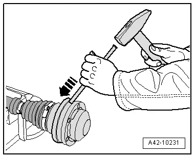
- Installing: Drive onto shaft with plastic hammer until compressed circlip seats.
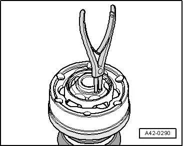
- Circlip must lie in joint chamfer when guiding in, guide with pliers if necessary.
- Grease quantity and type.
- The protective boot/outer CV joint sealing surfaces must be free of grease when installing.
- When installing the CV joint thinly coat the profile shaft splines with the grease used in the joint.
14 - Bolt
- Replace after removing
- Clean the threads in the CV joint with a thread tap.
- Drive Axle Threaded Connection, Loosening and Tightening. Refer to → Chapter "Drive Axle Threaded Connection, Loosening and Tightening".
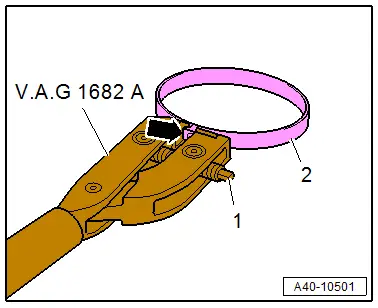
Tension the clamp using the Clampling Pliers -VAG1682A-.
- Attach the Clampling Pliers -VAG1682A- as shown.
- The jaws on the pliers must be centered -arrow- on the clamp -2-.
 Note
Note
- The spindle threads must turn easily. If necessary, coat with MoS2 lubricating grease.
- If difficult to tighten, for example because of dirty threads, the proper clamping force of the clamping sleeve will not be reached even when tightened to the specification.
- Tension the clamp by turning the spindle -1- with the torque wrench, at the same time do not tilt the clamping pliers.
- Tightening specification: 20 Nm.
Grease Quantity and Type
 Note
Note
- Grease joint when replacing CV boot.
- Pay attention to the grease type for the outer and inner joint. Refer to the Parts Catalog.
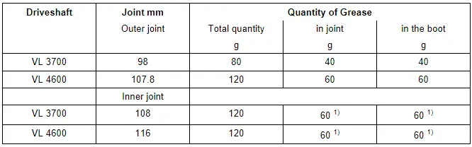
1) Apply grease through the ball races.
Drive Axle, Removing and Installing
Removing
- Loosen the connection between the drive axle and wheel hub. Refer to → Chapter "Drive Axle Threaded Connection, Loosening and Tightening".
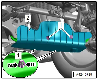
- Release the catches in direction of -arrows- and remove the locking pin -1- slightly.
- Remove the wind deflector -2- in the rear area downward from the transverse link.
- Unlock the catches again and remove the locking pin and the wind deflector.
Left Side of the Vehicle:
- Exhaust system without separating point: remove the rear muffler. Refer to → Rep. Gr.26; Exhaust Pipes/Mufflers; Overview - Muffler.
- Exhaust system with separating point: remove the exhaust pipe. Refer to → Rep. Gr.26; Exhaust Pipes/Mufflers; Overview - Muffler.
- Remove the bolts -arrows- and remove the heat shield -1-.
Continuation for All Vehicles:
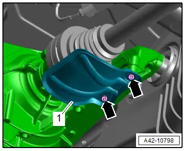
- Remove the bolts -arrows-, carefully remove the drive axle at the same time on versions with air suspension pay attention to the boot.
 Note
Note
Be careful not to damage the protective coating on the drive axle.
Installing
Install in reverse order of removal and note the following:
- Tighten the drive axle to wheel hub threaded connection. Refer to → Chapter "Drive Axle Threaded Connection, Loosening and Tightening".
Tightening Specifications
- Refer to → Chapter "Overview - Drive Axle"
Drive Axle Threaded Connection, Loosening and Tightening
Special tools and workshop equipment required
- Torque Wrench 80-400Nm -VAG1576-
- 19 mm inner hex socket, commercially available
Loosen the threaded connection between the drive axle/stub axle and wheel hub
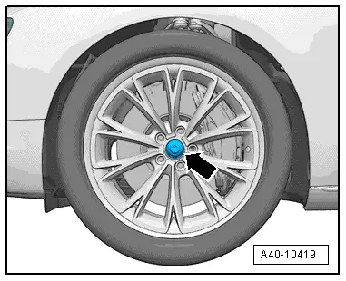
- With vehicle still resting on its wheels, loosen the bolt -arrow- a maximum of 90º using the 19 mm inner hex socket, otherwise the wheel bearing will be damaged.
- Lift the vehicle just enough so that the wheels are hanging free.
- Apply the brakes (a second technician required).
- Remove the bolt.
Tighten the threaded connection between the drive axle/stub axle and wheel hub
 Note
Note
- Replace bolt after removal.
- Before installing, clean the threads in the CV joint/stub axle with a thread tap.
- Wheels must not yet touch the ground when tightening the drive axle/stub shaft or the wheel bearing can be damaged.
- Apply the brakes (a second technician required).
- Tighten the bolt to 200 Nm.
- Lower the vehicle onto its wheels.
- Tighten bolt an additional 180º.
Drive Axle, Disassembling and Assembling
Drive Axle, Disassembling and Assembling, Outer CV Joint
Special tools and workshop equipment required
- Locking ring pliers, commercially available
- Sealant -D454 300 A2-. Refer to the Parts Catalog.
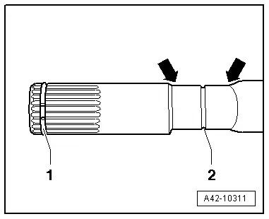
Removing Outer CV Joint
- Clamp the drive axle in a vise with protective covers.
- Open clamps.
- Slide back protective boot.
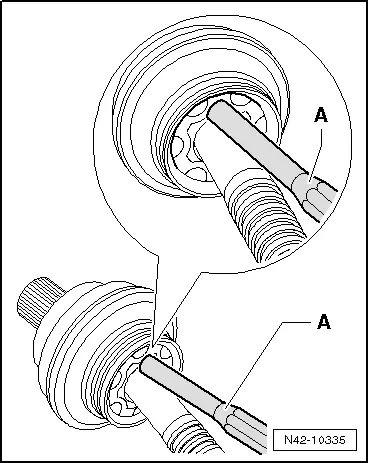
- Drive CV joint from drive axle using a drift -A-.
- The drift must be precisely positioned on the CV joint ball hub.
- Remove joint and protective joint boot.
- Remove the circlip -1- with the locking ring pliers.
 Note
Note
Ignore item -2-.

Installing the Outer CV Joint
- Push the joint protective boot and a new clamp onto the drive axle.
- Joints and protective joint boots must be free of grease.
- Push on the joint boot between the -arrows- in the groove -2- until it engages.
- Place drive axle grease evenly into the inside of the joint.

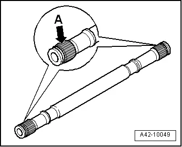
- Before installing joint, splines -arrow A- must be lightly coated with grease used in joint.
- Insert sealing ring in groove on shaft.

- Slide on CV joint up to sealing ring.
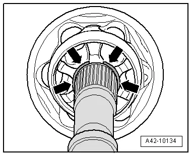
- Align sealing ring at center with opening upward -arrows-.
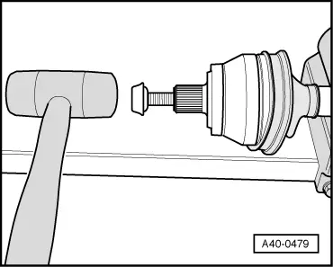
- Install the old bolt in the joint, as shown.
- Drive joint onto the drive axle with a plastic hammer until the circlip engages.
- Install the CV boot on the metal cap.
- Bleed the CV boot.
- Make sure the protective boot is seated on the joint correctly.
- The CV boot must fit in the groove and on joint contour.
- Tension the clamps on outer joint. Refer to → Fig. "Tension the clamp using the Clampling Pliers -VAG1682A-.".
Drive Axle, Disassembling and Assembling, Inner CV Joint
Special tools and workshop equipment required
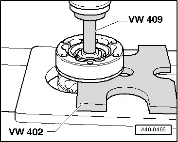
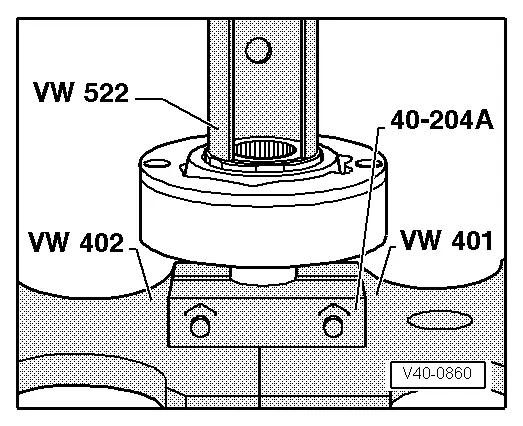
- Press Plate -VW401-
- Press Plate -VW402-
- Press Piece - Rod -VW409-
- Press Piece - Multiple Use -VW412-
- CV Joint Press Sleeve -VW522-
- Press Block -40-204A-
- Torque Wrench 1331 5-50Nm -VAG1331-
- Torque Wrench 80-400Nm -VAG1576-
- Locking ring pliers, commercially available
- Sealant - D 454 300 A2-
Removing the Inner CV Joint
- Clamp the drive axle horizontally in a vise with protective covers.
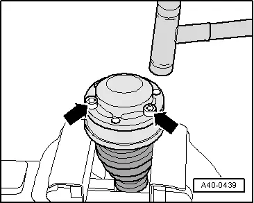
- Drive down the cover with a copper or brass mandrel in direction of -arrow-.
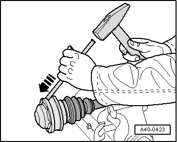
- Drive down the cap with a copper or brass mandrel in direction of -arrow-.
- Only open and remove the "small" protective boot clamp.
- Remove the circlip using the locking ring pliers.
- Mount the special tools as shown.
- Press inner CV joint off of drive axle.
- Remove the CV joint boot from the drive axle.
Installing the Inner CV Joint
- Slide the protective joint boot with the "small" clamp onto the drive axle.
- Before installing joint, splines -arrow A- must be lightly coated with grease used in joint.
- Mount the special tools as shown.
- The Press Block -40-204A- and clamping surfaces on drive axle must be free of grease.
- The chamfer on inner diameter of ball hub (splines) must face the contact shoulder on the drive axle.
- Press on joint until stop.
- Install the new circlip using the locking ring pliers.
- Check the seating of the circlip.
- Add half of the drive axle grease into the joint on the boot side before installing the joint protective boot.

- Grease the contact surfaces for the CV boot and cap.
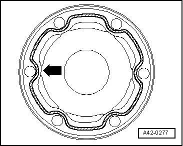
- Apply Sealant -D 454 300 A2--cross-hatched surface- on the clean surface on the inside of the CV boot cap.
- Sealant bead thickness: 2 to 3 mm.
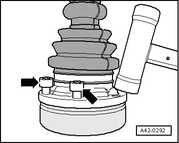
- Apply the inner sealant bead near the holes -arrow-.

- Align cap with bolts -arrows- with bolt holes.
 Note
Note
It must be aligned exactly because it cannot be aligned after driving on.
- Drive the cap on with a plastic hammer.
- Remove any excess sealant immediately.
- Apply the remaining drive axle grease through the ball paths in the CV joint.
- Grease the contact surface for the cover and for the CV joint.
- Apply Sealant -D 454 300 A2--cross-hatched surface- on the clean surface on the inside of the cover.
- Sealant bead thickness: 2 to 3 mm.
- Apply the inner sealant bead near the holes -arrow-.
- Align new cover with bolts -arrows- to bolt holes.
 Note
Note
It must be aligned exactly because it cannot be aligned after driving on.
- Drive cover on with a plastic hammer.
- Clear away leaking sealing immediately.
- Push on the CV boot and position it in the groove -2- between the -arrows- on the drive axle.
 Note
Note
Ignore -1-.
- Tightening clamps on inner joint. Refer to → Fig. "Tension the clamp using the Clampling Pliers -VAG1682A-.".
Outer CV Joint, Checking
- The outer CV joint and cap cannot be disassembled.
- The outer CV joint and cap can be only be inspected visually.
- The grease still in the joint must be free of water and dirt.
- If wear or damage is found on the ball journal surfaces, then the entire outer CV joint and cap must be replaced.
Grease quantities and types for drive shaft with outer constant velocity joint.
Inner CV Joint, Checking
It is necessary to disassemble the joint whenever replacing the grease or if the ball surfaces show wear or damage.
Disassembling
 Note
Note
Ball hub and joint are paired and should be identified before removal. Do not interchange cage allocation.
- Swivel the ball hub and ball cage.
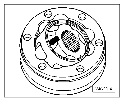
- Remove the joint in the direction of -arrow-.
- Remove the balls from the cage.
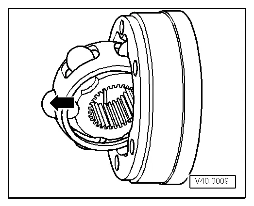
- Flip out ball hub from ball cage via running path of ball -arrows-.
- Check the joint, ball hub, ball cage and balls for small broken off depressions (pitting) and chafing.
 Note
Note
Excessive backlash in joint will be noticed as a knock during load changes. Joint must be replaced in such cases. Flattening and running marks of balls are no reason to replace joint.
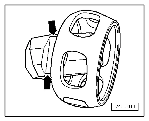
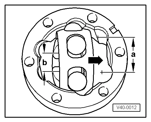
Assembling
- Insert ball hub into ball cage via two chamfers. The installation position is arbitrary. Press balls into cage.
- Insert hub with cage and balls upright into joint piece.
- When inserting, make sure that in each case the wide gap -a- at joint piece contacts narrow gap -b- at hub after swinging in.
- Chamfer on inner diameter of wheel hub (splines) must face toward drive axle.
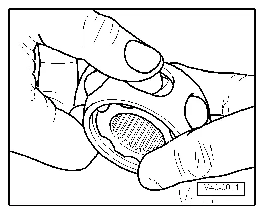
- Swing in ball hub, to do so swing out hub far enough from cage -arrows- so that the balls have the distance of the running paths.
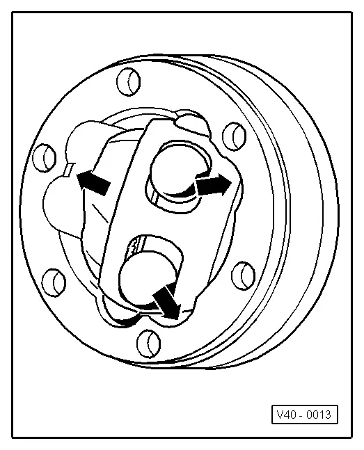
- Swing in hub with balls by pressing forcefully onto cage -arrow-.
Check the CV Joint for Function.
CV joint is properly assembled, if ball hub can be slid back and forth by hand over whole compensation length.
- Press grease into joint body.
Grease quantities and types, drive shaft with inner CV joint.