Audi Q7: Driver and Front Passenger Interior Locking Switch -E150-/-E198-, Removing and Installing
Removing
- Remove the interior door mechanism. Refer to → Body Interior; Rep. Gr.70; Front Door Trim Panels; Interior Door Mechanism, Removing and Installing.
- Open the clips in direction of -arrows- and remove the interior locking switch -1- outward.

Installing
Install in reverse order of removal.
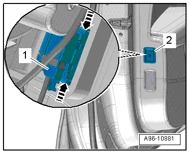
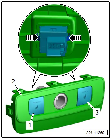
Driver and Front Passenger Seat Memory Settings Control Head -E464-/-E465-, Removing and Installing
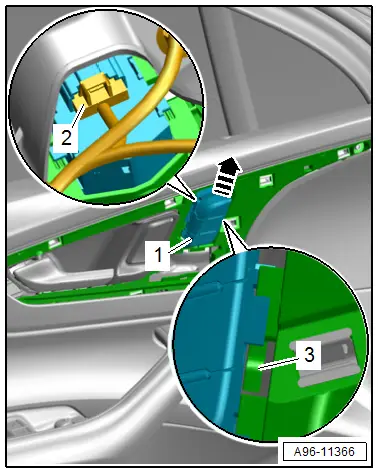
Removing
- Remove the decorative trim. Refer to → Body Interior; Rep. Gr.70; Front Door Trim Panels; Trim Molding, Removing and Installing.
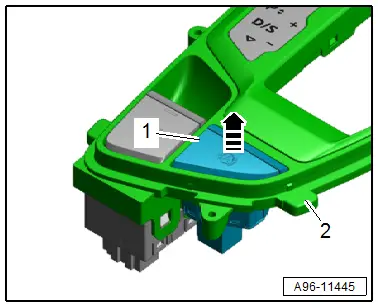
- Push the tab -3- slightly to the rear and remove the control head -1- from the mount at the same time in the direction of -arrow-.
- Disconnect the connector -2-.
- Remove the control head.
Installing
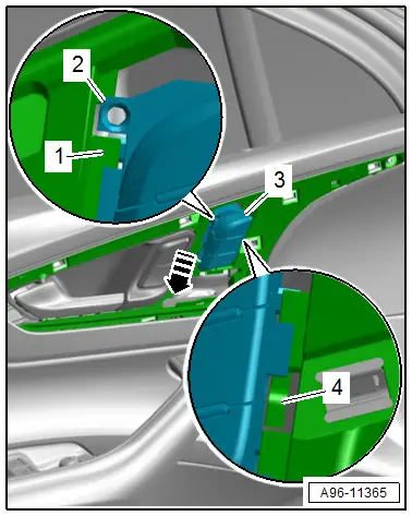
Install in the reverse order of removal while noting the following:
- Connect the connector.
- Place the control head -3- on the mount -1- and push on it until the tab -4- clicks into place -arrow-.
- The guide -2- must slide downward behind the mount.
Rear Lid Remote Release Button -E233-, Removing and Installing
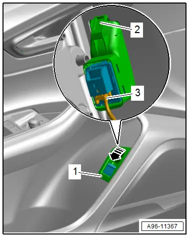
Removing
- Remove the front door trim panel. Refer to → Body Interior; Rep. Gr.70; Front Door Trim Panels; Front Door Trim Panel, Removing and Installing.
- Disconnect the connector -3-.
- Release the clip -2- and remove the trim -1- with the switch from the door trim panel -arrow-.
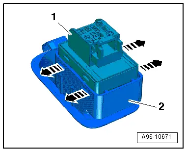
- Release the hooks in direction of -arrows- carefully with a small screwdriver.
- Remove the switch -1- toward the rear from the trim -2-.
Installing
Install in the reverse order of removal while noting the following:
- Press in the trim with the switch until the hooks engage in the mount.
Interior Monitoring and Vehicle Inclination Deactivation Button -E616-, Removing and Installing
Removing
- Remove the front door trim panel. Refer to → Body Interior; Rep. Gr.70; Front Door Trim Panels; Front Door Trim Panel, Removing and Installing.
- Disconnect the connector -1-.
- Release the retaining springs -arrows- and remove the button -2- from the door trim panel.
Installing
Install in reverse order of removal.
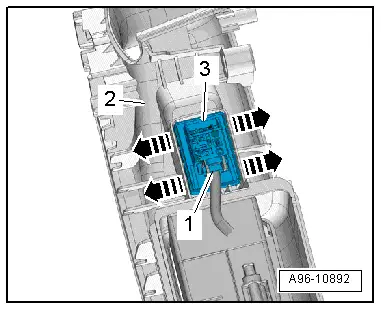
Rear Window Regulator Button in Rear Door, Removing and Installing
Removing
- Remove the pull handle/rear armrest. Refer to → Body Interior; Rep. Gr.70; Rear Door Trim Panels; Overview - Rear Door Trim Panel.
- Carefully release the retainers using a small screwdriver in direction of -arrows-.
- Remove the power window button -3- from the switch mount -2-.
- Disconnect the connector -1-.
Installing
Install in reverse order of removal.
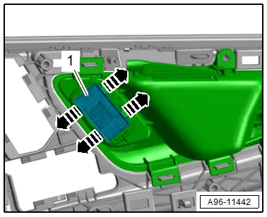
Left and Right Rear Interior Locking Switch -E273-/-E274-, Removing and Installing
Removing
- Remove the interior door mechanism. Refer to → Body Interior; Rep. Gr.70; Rear Door Trim Panels; Interior Door Mechanism, Removing and Installing.
- Open the clips in direction of -arrows- and remove the interior locking switch -1- outward.
Installing
Install in reverse order of removal.
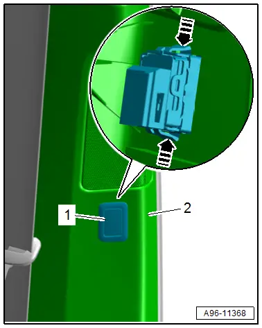
Air Ionization System Button -E677-, Removing and Installing
Removing
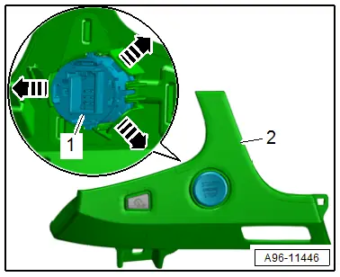
- Remove the lower B-pillar lower trim panel. Refer to → Body Interior; Rep. Gr.70; Vehicle Interior Trim Panels; B-Pillar Trim Panel, Removing and Installing.
- Release the clips in direction of -arrows- and press out the Air Ionization System Button -E677--1- from the B-pillar trim panel -2-.
Installing
Install in reverse order of removal.
Electromechanical Parking Brake Button -E538-/-AUTO HOLD- Button -E540-, Removing and Installing
Removing
- Remove the center console insert trim. Refer to → Body Interior; Rep. Gr.68; Center Console; Display Control Head Trim, Removing and Installing.
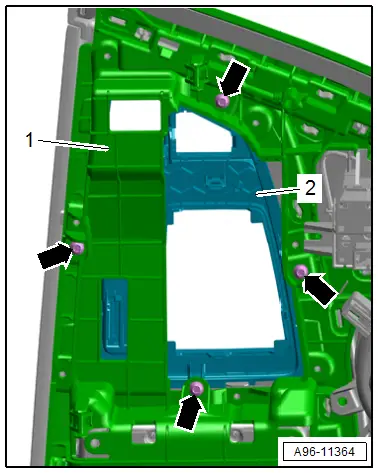
- Remove the bolts in direction of -arrows-.
- Remove the selector lever transmission range display -2- from the center console insert -1-.
Electromechanical Parking Brake Button -E538-:
- Carefully release the retainers using a small screwdriver in direction of -arrows-.
- Press the button -1- out of the selector lever transmission range display -2-.
-AUTO HOLD- Button -E540-:
- Press the button -1- out of the selector lever transmission range display -2--arrow-.
Installing
Install in reverse order of removal.
Access/Start Authorization Button -E408-, Removing and Installing
Removing
- Remove the access/start authorization switch trim. Refer to → Body Interior; Rep. Gr.70; Instrument Panel; Access/Start Authorization Switch Trim, Removing and Installing.
- Release the retainers in direction of -arrows-.
- Remove the button -1- from the mount in the access/start authorization switch trim -2-.
Installing
Install in reverse order of removal.
Left and Right Seat Heating Button -E653-/-E654-, Removing and Installing
Removing
- Remove the rear seat heating socket/button trim. Refer to → Body Interior; Rep. Gr.68; Center Console; Display Control Head Trim, Removing and Installing.
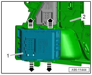
- Release the clips -arrows-.
- Remove the switches -1 and 3- from the cover -2-.
Installing
Install in reverse order of removal.

