Audi Q7: Rear Lid Lock Button in Luggage Compartment -E406-, Removing and Installing
- Depending on vehicle equipment the Locking Mechanism Button in the Rear Lid -E806- is integrated in the Rear Lid Lock Button in Luggage Compartment -E406-. If faulty the complete button unit must be replaced.
Removing
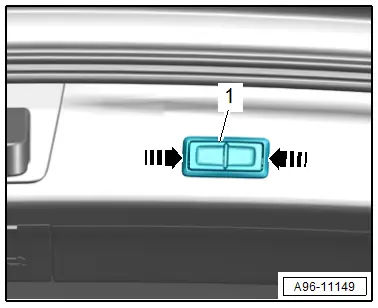
- Release the clips on the button -1- in direction of -arrows-.
- Remove the button from the rear lid trim panel.
- Disconnect the connector.
TIP
Remove the rear lid lower trim panel if the button cannot be removed as described. Refer to → Body Interior; Rep. Gr.70; Luggage Compartment Trim Panels; Rear Lid Lower Trim Panel, Removing and Installing.
Installing
Install in reverse order of removal.
Rear Lid Warning Buzzer -H32-, Removing and Installing
Removing
- Remove the rear roof panel trim. Refer to → Body Interior; Rep. Gr.70; Roof Trim Panels; Roof End Strip, Removing and Installing.
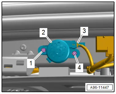
- Remove the bolts -1 and 4-.
- Remove the buzzer -2- with the expanding clips.
- Disconnect the connector -3-.
Installing
Install in reverse order of removal.
Rear Lid Contact Switch, Removing and Installing
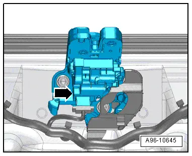
The rear lid contact switch -arrow- is located in the rear lid lock and cannot be replaced separately if faulty.
- Replace the rear lid lock. Refer to → Body Exterior; Rep. Gr.55; Rear Lid; Latch, Removing and Installing.
Sunroof Button -E325-, Removing and Installing
Removing
- Remove the front interior lamp/reading lamp. Refer to → Chapter "Front Interior Lamp/Reading Lamp, Removing and Installing".
- Remove the bolts -arrows-.
- Remove the button -1- from the front interior/reading lamp -2-.
Installing
Install in reverse order of removal.
Tightening Specifications
- Refer to → Fig. " Sunroof Button -E325- Tightening Specification:"
Front Interior Lamp/Reading Lamp, Removing and Installing
Special tools and workshop equipment required
- Trim Removal Wedge -3409-
Removing
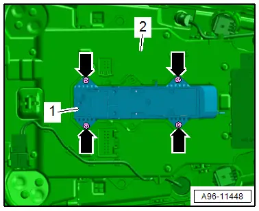
- Pry out the front roof module -1- with the -3409- beginning at the left front on the headliner, to do so push in the trim removal wedge in the area of the spring between the headliner and the front roof module.
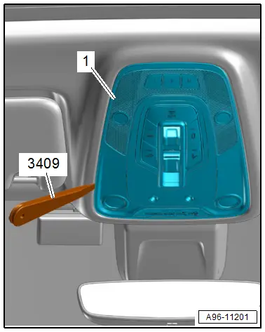
- The marking shows the position of the springs -arrows-.
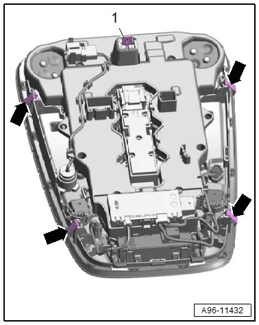
- The clamp -1- is removed by prying out of the body.
- Disconnect the connectors and free up the wiring harness.
Installing
Install in the reverse order of removal while noting the following:
- The front roof module must be completely replaced if one of the LEDs is faulty
- Insert the front roof module into the roof cutout and press until it audibly engages.
Rear Interior Lamp/Reading Lamp, Removing and Installing
Rear Interior Lamp/Reading Lamp, Removing and Installing
Special tools and workshop equipment required
- Wedge Set -T10383-
Removing
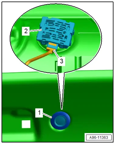
- Remove the interior lamp/reading lamp -1- from the roof using Wedge Set - Wedge 1 -T10383/1- in direction of -arrows-.
- Disconnect the connector.
Installing
Install in the reverse order of removal while noting the following:
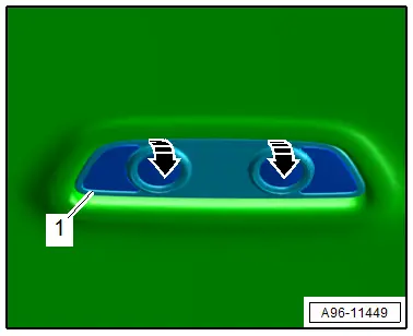
- Insert the interior lamp/reading lamp into the roof cutout and clip it in.
Rear Interior Lamp/Reading Lamp, Removing and Installing, Vehicles with Panorama Sliding Sunroof
Removing
- Lower the headliner. Refer to → Body Interior; Rep. Gr.70; Roof Trim Panels; Headliner, Removing and Installing.
- Pry up the frame -1-.
- Remove the interior lamp -2-.
- Disconnect the connector -3-.
Installing
Install in reverse order of removal.
Garage Door Opener Control Head -E284-, Removing and Installing
Removing
- Remove the front interior lamp/reading lamp. Refer to → Chapter "Front Interior Lamp/Reading Lamp, Removing and Installing".
- Remove the Anti-Theft Alarm System Sensor -G578-, if equipped. Refer to → Chapter "Anti-Theft Alarm System Sensor -G578-, Removing and Installing".
- Carefully push the catches to the side in direction of -arrows-.
- Remove the control head -2- from the front interior lamp/reading lamp -1-.
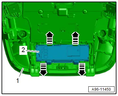
Installing
Install in reverse order of removal.

