Audi Q7: Driver Door Control Module -J386- and Front Passenger Door Control Module -J387-, Removing and Installing
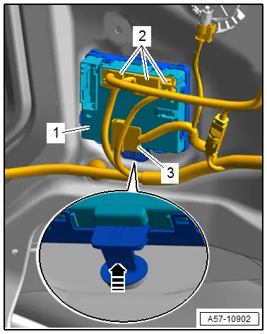
Removing
- Remove the front door trim panel. Refer to → Body Interior; Rep. Gr.70; Front Door Trim Panels; Front Door Trim Panel, Removing and Installing.
- Disconnect the connectors -2-.
- Free up the connector -3- on the door control module -1-.
- Press the catch in the -direction of the arrow- and disengage the door control module from the door body.
Installing
Install in reverse order of removal.
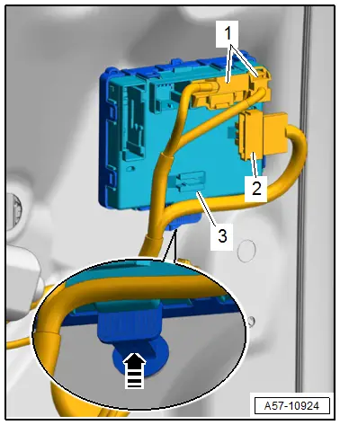
Left Rear Door Control Module -J388- and Right Rear Door Control Module -J389-, Removing and Installing
Removing
- Remove the rear door trim panel. Refer to → Body Interior; Rep. Gr.70; Rear Door Trim Panels; Rear Door Trim Panel, Removing and Installing.
- Disconnect the connectors -1-.
- Free up the connector -2- on the door control module.
- Press the catch in the direction of the -arrow- and disengage the door control module from the door body.
Installing
Install in reverse order of removal.
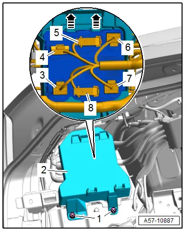
Comfort System Central Control Module -J393-, Removing and Installing
Removing
- Remove the fuse panel F and move it to the side with the wires still connected. Refer to → Electrical Equipment; Rep. Gr.97; Relay Panels, Fuse Panels and E-Boxes; Component Location Overview - Relay Panels, Fuse Panels and E-Boxes.
- Vehicles with high-voltage system, equipped on some models: Remove the subwoofer. Refer to → Communication; Rep. Gr.91; Sound System; SubwooferR211, Removing and Installing.
- Remove the nuts -1-.
- Remove the mount -2- at the same time guide out the body.
- Disconnect the connectors -3 through 8-.
- Release the retainers -arrows- and guide the central control module out of the mount.
Installing
Install in reverse order of removal.
Tightening Specifications
- Refer to → Fig. "Tightening Specifications for Comfort System Central Control Module -J393- Mount"
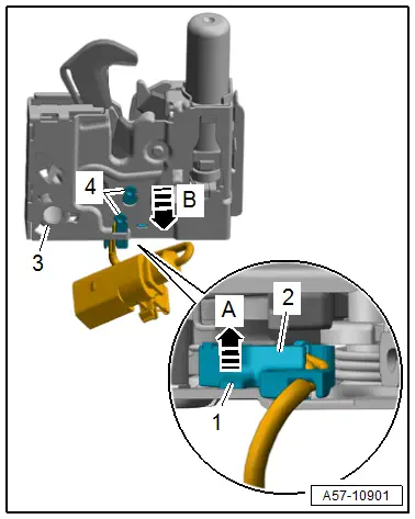
Engine Hood Contact Switch -F266-, Removing and Installing
Removing
- Remove the front latch. Refer to → Chapter "Latch, Removing and Installing".
- Lift the retaining tab -1--arrow A-.
- Disengage the contact switch -2- from the latch -3--arrow B- and remove.
Installing
Install in reverse order of removal and note the following:
- The guide pins -4- on the contact switch must inserted correctly in the front latch.

