Audi Q7: Front Left Relay and Fuse Panel, Removing and Installing
Fuse Panel B -SB-, Removing and Installing
Special tools and workshop equipment required
- Fiber-Optic Repair Set - Connector Protective Caps -VAS6223/9- from Fiber-Optic Repair Set -VAS6223B-
Removing
- Loosen and fold back the left front carpet. Refer to → Body Interior; Rep. Gr.70; Vehicle Interior Trim Panels; Carpet, Removing and Installing.
- Turn off the ignition and disconnect the ground cable from the battery. Refer to → Chapter "Battery, Disconnecting and Connecting".
- Disconnect the connectors -1 to 4-, the antenna wire -5- and the connector -4- for the fiber-optic cable.
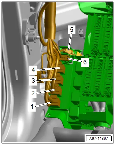
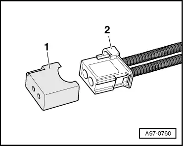
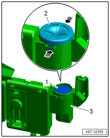
- Seal the open wiring harness connector -2- of the fiber-optic cable with the Fiber-Optic Repair Set - Connector Protective Caps -VAS6223/9--1-.
TIP
The protective cap prevents contamination of or mechanical damage to the front surface of the fiber-optic cable which would impair light transmission.
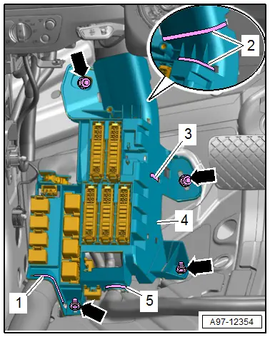
- Remove the nuts -arrows-.
- Cut the cable ties -1, 2, 3 and 5-.
- Remove the fuse panel B -3- from the threaded pin.
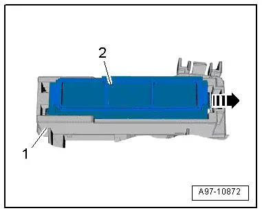
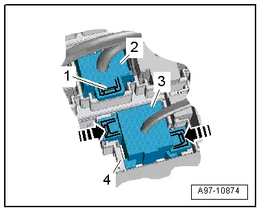
- Release the tab in direction of -arrow-, push fuse panel -2- to the rear and disengage it from the fuse panel B -1-.
- Open the clip and remove the auxiliary fuse panel -2-.
- Release the clips in direction of -arrows- and remove the relay -1- and the control modules from the relay panels.
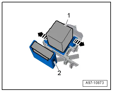
- Open the clips in direction of -arrows- and press the relay panel -3- toward the rear and out of the bracket -4-.
- Open the clip -1- and remove the connector terminal -2- from the bracket.
- Remove the fuse panel B.
Installing
Install in the reverse order of removal while noting the following:
- Connect the battery. Required actions.
Tightening Specifications
- Refer to → Chapter "Overview - Component Location Relay Panel, Fuse Panel, E-Boxes, Left Footwell"
Fuse Panel, Removing and Installing
Removing
- Remove the fuse panel B. Refer to → Chapter "Fuse Panel B -SB-, Removing and Installing".
- Unlock the release and remove it from the fuse panel.
- Remove the fuses from the fuse panel.
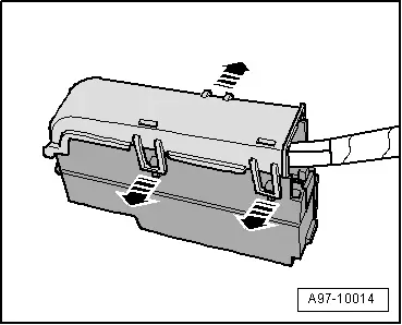
- Open the clips in direction of -arrows- and remove the fuse panel cover.
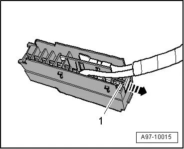
- Pull off retaining strip -1- for the connectors in direction of -arrow- and remove the connectors from the plug-in socket
TIP
Check the exact assignment in the current wiring diagram. Refer to → Wiring diagrams, Troubleshooting & Component locations.
Installing
Install in reverse order of removal.
Suppressor -C24-, Removing and Installing
Removing
- Remove the terminal 30 wire junction. Refer to → Chapter "Terminal 30 Wire Junction -TV2-, Removing and Installing".
- Release the retainers in direction of -arrows- and remove the cover -3-.
- Push the suppressor -1- upward and out of the housing -3- from below and remove it.
Installing
Install in reverse order of removal.

