Audi Q7: Wire Junction, Removing and Installing
Wire Junction -TV1-, Removing and Installing, Vehicles without High-Voltage System
Removing
- Disconnect the ground cable from the battery when the ignition is switched off. Refer to → Chapter "Battery, Disconnecting and Connecting".
- Remove the front sill panel. Refer to → Body Interior; Rep. Gr.70; Vehicle Interior Trim Panels; Sill Panel, Removing and Installing.
- Remove the A-pillar lower trim panel. Refer to → Body Interior; Rep. Gr.70; Vehicle Interior Trim Panels; A-Pillar Trim Panel, Removing and Installing.
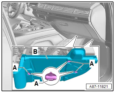
- Remove the screw clips -A-.
- Loosen and remove the insulation -B- from the A/C unit air intake manifold.
- Push the carpet in the area of the footwell to the side as far as possible.
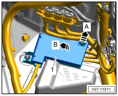
- Release the retainer in direction of -arrow A- and open the cover -1- in direction of -arrow B-.
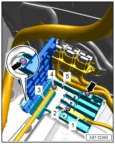
- Remove the nuts -2 and 4- and free up the wires -1 and 3-.
- Remove the nuts -arrows-.
- Remove the E-box -5-.
Installing
Install in the reverse order of removal while noting the following:
- Connect the battery. Required actions.
Tightening Specifications
- Refer to → Chapter "Overview - Component Location Relay Panel, Fuse Panel, E-Boxes, Right Footwell"
Terminal 30 Wire Junction 3 -TV28-, Removing and Installing, Vehicles with High-Voltage System
Removing
- Disconnect the ground cable from the battery when the ignition is switched off. Refer to → Chapter "Battery, Disconnecting and Connecting".
- Remove the front sill panel. Refer to → Body Interior; Rep. Gr.70; Vehicle Interior Trim Panels; Sill Panel, Removing and Installing.
- Remove the A-pillar lower trim panel. Refer to → Body Interior; Rep. Gr.70; Vehicle Interior Trim Panels; A-Pillar Trim Panel, Removing and Installing.
- Remove the screw clips -A-.
- Loosen and remove the insulation -B- from the A/C unit air intake manifold.
- Push the carpet in the area of the footwell to the side as far as possible.

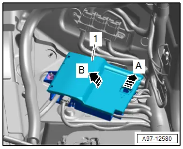
- Release the retainer in direction of -arrow A- and open the cover -1- in direction of -arrow B-.
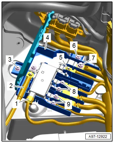
- Disconnect the connector -1-.
- Remove the wires -2 and 7-.
- Remove the nuts -5, 8 and 9- and free up the wires.
- Remove the nuts -3 and 6-.
- Remove the E-box -4-.
Installing
Install in reverse order of removal and note the following:
- Connect the battery. Required actions.
Tightening Specifications
- Refer to → Chapter "Overview - Component Location Relay Panel, Fuse Panel, E-Boxes, Right Footwell"
Terminal 30 Wire Junction -TV2-, Removing and Installing
Removing
- Turn off the ignition and disconnect the ground cable from the battery. Refer to → Chapter "Battery, Disconnecting and Connecting".
- Remove the terminal 30 wire junction 2 and move to the side with the lines still connected. Refer to → Chapter "Terminal 30 Wire Junction 2 -TV22-".
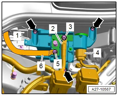
- Disconnect the connector -4-.
- Remove the nuts -3 and 5- and free up the wires -2 and 6-.
- Remove the nuts -arrows-.
- Remove the wire junction -1- from the threaded pins.
Installing
Install in reverse order of removal.
Tightening Specifications
- Refer to → Chapter "Overview - Component Location Relay Panel, Instrument Panel, E-Boxes Engine Compartment"
Terminal 30 Wire Junction 2 -TV22-
Removing
- Turn off the ignition and disconnect the ground cable from the battery. Refer to → Chapter "Battery, Disconnecting and Connecting".
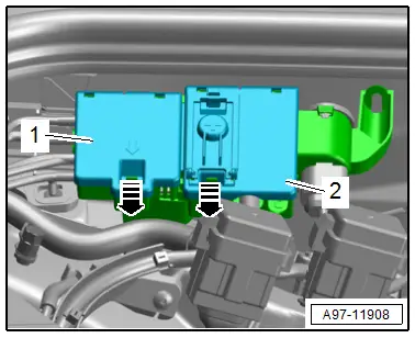
- Release the retainers in direction of -arrows-.
- Open the cover in the sequence -2 and 1-.
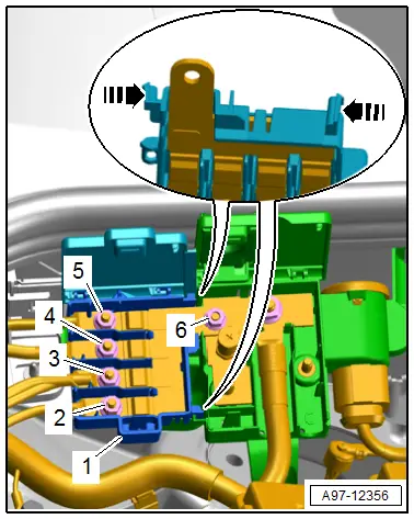
- Remove the wires -2 to 5- and free them up.
- Remove the nut -6-.
- Remove the wire junction -1- from the threaded pins.
Installing
Install in reverse order of removal.
Tightening Specifications
- Refer to → Chapter "Overview - Component Location Relay Panel, Instrument Panel, E-Boxes Engine Compartment"

