Audi Q7: General Information
Safety Precautions
Check for Technical Bulletins that may supersede any information included in this manual.
 WARNING
Failure to follow these instructions may result in personal injury or possible death.
Check the Technical Bulletins for information, cautions and warnings that may supersede or supplement any information included in this manual.
When performing the drive cycle operation, pay strict attention to driving conditions and observe and obey all posted speed limits.
Test equipment must always be secured to the rear seat and operated by a second person. If test and measuring equipment is operated from the passenger seat, the person seated could be injured in the event of an accident involving deployment of the passenger-side airbag.
The fuel system is under pressure! Before opening the fuel system, place rags around the connection area. Then release pressure by carefully loosening the connection.
The engine section of the fuel system, after the high pressure pump, is under extremely high pressure! When working on engine or fuel injection system, fuel pressure must be relieved to residual pressure before opening high pressure components. Refer to the Service Manual for the proper procedure.
If the battery has not been disconnected, the fuel pump fuse must be removed before opening the fuel supply system as the fuel pump may be activated by the driver's door contact switch.
Testing of the EVAP and ORVR systems can result in the escape of explosive fuel vapor. Do not smoke while testing the EVAP system, and make sure the area you are working in is well ventilated.
Observe the following for all procedures, especially in the engine compartment due to lack of room:
- Route lines of all types (e.g. for fuel, hydraulic, EVAP canister system, coolant and refrigerant, brake fluid, vacuum) and electrical wiring so that the original path is followed.
- Watch for sufficient clearance to all moving or hot components.
- Do not touch or disconnect the Ignition Coils, ignition wires, connecting parts or adapter cables when the ignition is on or the engine is running or turning at starting RPM.
- Only disconnect and reconnect wires for injection and ignition system, including test leads, when the ignition is turned off.
When removing and installing components from full or partially full fuel tanks, observe the following:
- The fuel tank must only be partially full. How much fuel can remain in the fuel tank may be read in the respective work description. Empty the fuel tank if necessary.
- Before starting work, switch on the exhaust extraction system and place an extraction hose close to the installation opening of the fuel tank to extract escaping fuel fumes. If no exhaust extraction system is available, a radial fan (as long as motor is not in air flow) with a displacement greater than 15 m3/h can be used.
- Prevent fuel from contacting the skin! Wear fuel-resistant gloves!
When servicing the engine control module (ECM), it may be necessary to use a heat gun. The heat gun, shear bolts, and parts of the protective housing will become extremely hot. Use extreme caution when working with or handling these parts to avoid personal injury.
Observe operating instructions when working with a heat gun. To prevent damage (burning) to the wiring and harness connections, insulation and the electronic components, perform outlined work steps exactly!
The cooling system is under pressure. To avoid scalding, use caution when opening the cooling system and servicing cooling system components!
 Caution
The battery must only be disconnected and connected with the ignition switched off. Otherwise, the engine control module (ECM) can be damaged.
The use of nails, paper clips, or another unauthorized materials to back-probe harness connectors is strictly prohibited and may cause damage to the harness connectors, terminal ends or to a component. Use only the manufacturers test lead kit or an equivalent aftermarket test lead kit for back-probing all harness connectors.
Do not use sealants containing silicone. Particles of silicone drawn into the engine, will not be burned in the engine and will damage the oxygen sensors.
Secure all hose connections with the correct hose clips (the same as original equipment).
If engine is to be cranked without starting (for example; as part of a compression test), remove the fuses for the voltage supply of ignition coils and the fuel injectors.
An electrostatic charge can lead to functional problems of electrical components of the engine, transmission and selector lever mechanism. Touch a grounded object, e.g. a water pipe or a hoist, before working on electrical components.
Do not make direct contact with harness connector terminals.
Use only gold-plated terminals when servicing any component with gold-plated harness connector terminals.
Clean Working Conditions
Even minor contaminations can lead to malfunctions in the fuel injection system. When working on the fuel supply/injection system, pay careful attention to the following rules of cleanliness:
- Thoroughly clean all connections and the surrounding area before disconnecting.
- Place removed parts on a clean surface and cover. Use lint-free cloths.
- Carefully cover opened components or seal, if repairs are not performed immediately.
- When the system is open, do not work with compressed air. Do not move vehicle unless absolutely necessary.
- Install clean components: Remove the parts being replaced immediately prior to installation of the new parts. Do not use parts that have been stored unpacked (e.g. in tool boxes etc.).
- Electrical connectors that have been disconnected: Protect from dirt and moisture. Make sure connections are clean and dry when reconnecting.
High Voltage System General Warnings
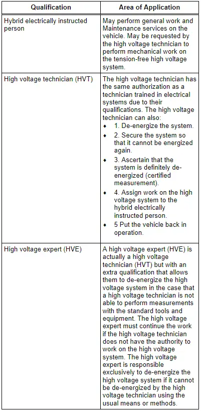
Before performing any work on the high voltage system, always check with the importer if there are any questions regarding the terms "technician trained in electrical systems", "high voltage technician", "high voltage expert", "high voltage systems", or "hybrid systems". Qualifications necessary for most of these terms are also provided below.
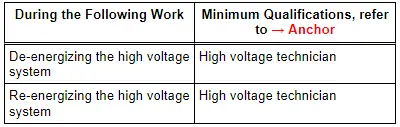
Before beginning work on the high voltage system, a high voltage technician, must de-energize the high voltage system. Refer to appropriate repair manual for high voltage system de-energizing.
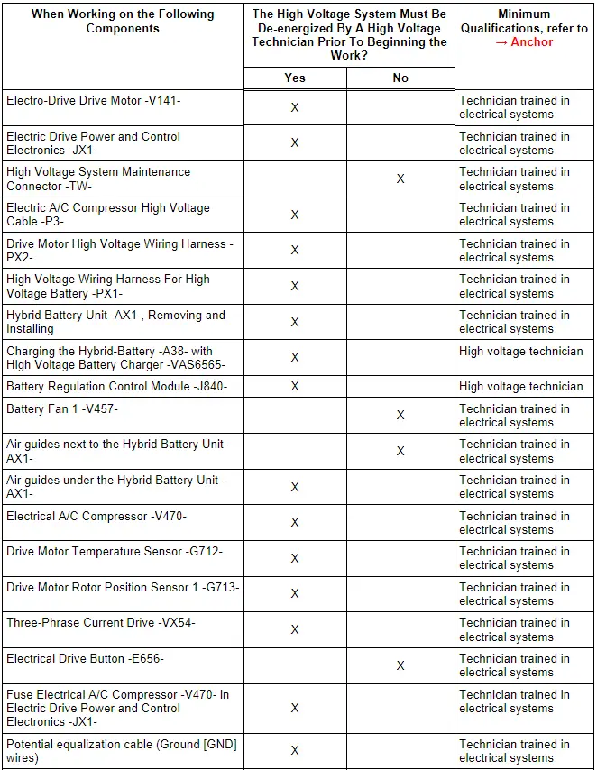
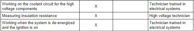
For a list of work procedures requiring the high voltage system to be de-energized, refer to the tables listed below in: Working on the High Voltage System, Conventional Work Near High Voltage Components, and General Work.
 WARNING
Read and follow the information below when de-energizing the high voltage system to reduce the risk of fatal injury.
- Only a qualified technician (high voltage technician) should disable the high voltage system.
- The high voltage technician (HVT) makes sure the system is de-energized and cannot be re-energized again.
- The high voltage technician assures that the system cannot be re-energized again by safely storing the key, the High Voltage System Maintenance Connector -TW- and the pilot line connector.
- The high voltage technician (HVT) puts a sign on the vehicle saying the voltage is disabled.
- Only hybrid electrically instructed persons may perform all work (maintenance, tire changing, Convenience System) on vehicles with a high voltage system. If there is any uncertainty, discuss with the responsible high voltage technician.
- A high voltage technician must disable the system before any work can be performed on the high voltage electrical system or any other service work to the body.
- Only a high voltage expert (HVE) may perform repairs to the vehicle if it is not possible to disable the high voltage electrical system.
- Individuals with electrical medical equipment must not work on vehicles with a high voltage electrical system. Examples of electrical medical equipment include pain medication pumps, implanted heart defibrillators, pacemakers, insulin pumps and hearing aids.
 WARNING
Working with high voltage cables:
- Do not support yourself or lay tools on the high voltage cables or on any of its components.
- When working near high voltage components and high voltage cables, do not use tools that generate heat, that have sharp edges or that are used for cutting or shaping, such as welding, soldering, hot air or thermal adhesive equipment.
- When working near high voltage components and high voltage cables, do not use tools that generate heat such as welding, soldering, hot air or thermal adhesive equipment.
- Do not excessively bend or flex high voltage cables.
- Always contact a high voltage technician (HVT) if there are questions or if something is not clearly understood.
Check the contact surfaces on the potential equalization cables before installation.
The contact surfaces must be clean. There must be no rust or grease on them.
Follow all guidelines for clean working conditions.
Observe the following precautions when working on the high voltage system:
- Only technicians who are trained in electrical systems should work on high voltage system (hybrid) vehicles.
- When working on a hybrid vehicle, always inspect the hybrid components in the area where the work is being performed.
- Do not excessively bend or flex high voltage cables.
- Always contact a high voltage technician or a high voltage expert specializing in electrical systems if something is not understood or if there are questions.
- All the work described below is referencing removing, installing and replacing the individual components.
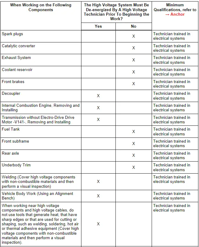
Working on the High Voltage System
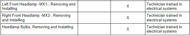
Conventional Work Near High Voltage Components
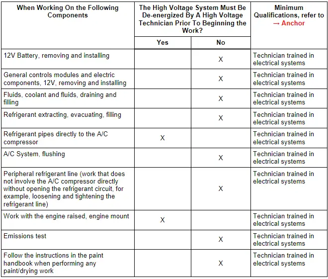
General Work
Qualification Explanation