Audi Q7: Refrigerant Lines in Plenum Chamber, Removing and Installing
 Caution
This procedure contains mandatory replaceable parts. Refer to component overview prior to starting procedure.
Mandatory Replacement Parts
- O-ring - Front Expansion Valve to Refrigerant Line - High Pressure Side
 Caution
Danger due to refrigerant coming out under pressure.
Danger of frost bite to skin and other parts of the body.
Only loosen the connection point bolts when the refrigerant circuit is empty.
Removing
- Turn off the ignition.
- Discharge the refrigerant circuit. Refer to → Refrigerant R134a Servicing; Rep. Gr.87; Refrigerant Circuit.
- Remove the plenum chamber cover. Refer to → Body Exterior; Rep. Gr.50; Bulkhead; Plenum Chamber Cover, Removing and Installing.
 Note
Note
To prevent water from running via intake shaft into the heater and A/C unit when plenum chamber cover is installed, plenum chamber cover must not be damaged. In addition the plenum chamber cover must engage correctly and completely in the plenum chamber cover. Refer to → Body Exterior; Rep. Gr.50; Bulkhead; Plenum Chamber Cover, Removing and Installing.
- Remove the washer fluid reservoir filler tube. Refer to → Electrical Equipment; Rep. Gr.92; Windshield Washer System; Washer Fluid Reservoir, Removing and Installing.
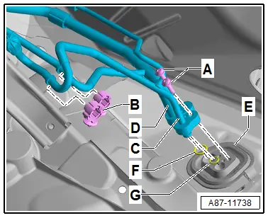
- Remove the bolts -A-. Refer to → Chapter "Overview - Refrigerant Lines in Plenum Chamber and Front Expansion Valve" for the tightening specification.
- Loosen both refrigerant lines to the expansion valve -C and D- from the bracket -B- and the pass-through -E-.
 Note
Note
Immediately seal off any open line connections and connection points with clean plugs, for example, taken from the Engine Bung Set -VAS6122-.
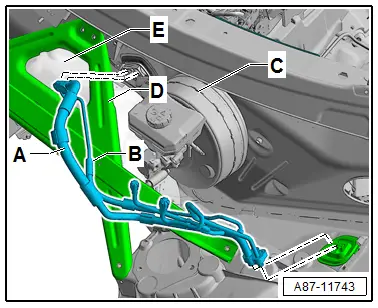
- Remove the tower brace -D-. Refer to → Suspension, Wheels, Steering; Rep. Gr.40; Suspension Strut and Upper Control Arm; Tower Brace, Removing and Installing.
- Loosen the lower plenum chamber bulkhead -E- from the vehicle and move to the side (do not remove). Refer to → Body Exterior; Rep. Gr.50; Bulkhead; Overview - Bulkhead.

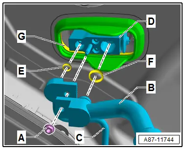
- Remove the nut -A-. Refer to → Chapter "Overview - Refrigerant Lines in Plenum Chamber and Front Expansion Valve" for the tightening specification.
- Remove both refrigerant lines -B and C- from the front expansion valve -D-. Refer to → Chapter "Refrigerant Lines, Disconnecting from Front Expansion Valve and Reconnecting"
- Remove both refrigerant lines -A and B- toward the left fender (under the brake booster -C-).
Installing
Install in reverse order of removal. Note the following:
- Replace all O-rings (in this illustration -E and F-) there are different versions. Refer to the Parts Catalog.
 Note
Note
Coat the O-ring seals lightly with refrigerant oil prior to installation. Refer to → Chapter "Refrigerant Circuit Seals".
- Always clean the expansion valve, pass-through, and refrigerant lines on the connection area and check them for damage.
 Note
Note
Install the refrigerant lines such that they are not strained.
- Check the routing of the refrigerant lines after attachment. They must be inserted in the provided brackets in a tension-free manner and must not come in contact with other components.
- Reinstall removed components in the reverse order and reattach detached components.
- Evacuate and charge the refrigerant circuit. Refer to → Refrigerant R134a Servicing; Rep. Gr.87; Refrigerant Circuit.
- Turn on the ignition.
- Retrieve the Front A/C Display Control Head -E87- DTC memory and if necessary delete the displayed error. Refer to Vehicle Diagnostic Tester in the "Guided Fault Finding" function.
- Operate the A/C system after charging the refrigerant circuit. Refer to → Chapter "A/C System, Starting after Charging Refrigerant Circuit".

 Note
Note
Note the information regarding operating the A/C system after filling. Refer to → Refrigerant R134a Servicing; Rep. Gr.87; A/C System, General Information.

