Audi Q7: Heated Oxygen Sensor
Overview - Heated Oxygen Sensor
 Note
Note
- Coat the new heated oxygen sensors with an assembly paste.
- Only the thread may be coated with hot bolt paste on a used oxygen sensor. Refer to the Parts Catalog
- Assembly paste or hot bolt paste must not enter the slots on the sensor body.
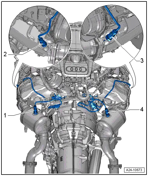
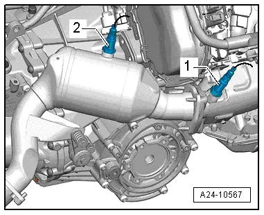
1 - Oxygen Sensor 2 after Catalytic Converter -G131-
- 55 Nm
- With Heater for Oxygen Sensor 2 after Catalytic Converter -Z30-
- Removing and installing. Refer to → Chapter "Heated Oxygen Sensor 2 -G108-/ Oxygen Sensor 2 after Catalytic Converter -G131-, Removing and Installing".
2 - Heated Oxygen Sensor 2 -G108-
- 55 Nm
- With Oxygen Sensor 2 Heater -Z28-
- Removing and installing. Refer to → Chapter "Heated Oxygen Sensor 2 -G108-/ Oxygen Sensor 2 after Catalytic Converter -G131-, Removing and Installing".
3 - Heated Oxygen Sensor -G39-
- 55 Nm
- With Oxygen Sensor Heater -Z19-
- Removing and installing. Refer to → Chapter "Heated Oxygen Sensor -G39-, Removing and Installing".
4 - Oxygen Sensor after Catalytic Converter -G130-
- 55 Nm
- With Heater For Oxygen Sensor 1 after Catalytic Converter -Z30-
- Removing and installing. Refer to → Chapter "Heated Oxygen Sensor -G39-, Removing and Installing".
Heated Oxygen Sensor, Removing and Installing
Heated Oxygen Sensor -G39-, Removing and Installing
Special tools and workshop equipment required
- Ring Wrench 7-Piece Set -3337-
Removing
 Note
Note
During installation, all cable ties must be installed at the same location.
- Remove the Throttle Valve Control Module -J338-. Refer to → Chapter "Throttle Valve Control Module -J338-, Removing and Installing".
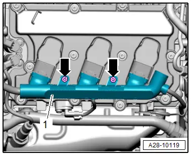
- Remove the bolts -arrows- and disconnect the connectors on the ignition coils.
- Lay the wiring harness -1- slightly underneath.
 Note
Note
The installation position for the cylinder bank 2 (left) is shown in this and the following illustration.
- Disconnect the connector -1- from Camshaft Position Sensor 3 -G300-.
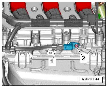
- Disconnect the connectors -1-.
 Note
Note
Ignore -2-.

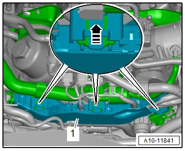
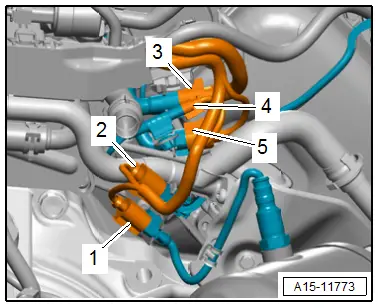
- Free up the wiring harness.
- Release the catches in direction of -arrow-, remove the wiring duct toward the rear and push to the side.
- Remove the connectors -3 and 4- from the bracket and move to the side.
- Remove the connector -5- from the bracket and move to the side.
 Note
Note
Ignore -1 and 2-.
- Remove the Heated Oxygen Sensor -G39--1- with the Ring Wrench Set - Oxygen Sensor Probe Socket -3337/7-.
 Note
Note
- The installed position is shown in the illustration with the engine removed.
- Ignore -2-.
Installing
Install in reverse order of removal and note the following:
 Note
Note
- Coat the new heated oxygen sensors with an assembly paste.
- When installing the previous oxygen sensor, coat the thread with hot bolt paste. Refer to the Parts Catalog.
- Assembly paste or hot bolt paste must not enter the slots on the sensor body.
- The wire for the heated oxygen sensor must always be secured back at the same positions when installing so that the heated oxygen sensor cable does not come in contact with the exhaust pipe.
- Install the Throttle Valve Control Module -J338-. Refer to → Chapter "Throttle Valve Control Module -J338-, Removing and Installing".
- Connections and wire routing. Refer to → Wiring diagrams, Troubleshooting & Component locations.
Tightening Specifications
- Refer to → Chapter "Overview - Heated Oxygen Sensor"
- Refer to → Chapter "Overview - Ignition System"
Oxygen Sensor after Three Way Catalytic Converter -G130-, Removing and Installing
Special tools and workshop equipment required
- Ring Wrench 7-Piece Set -3337-
Removing
 Note
Note
During installation, all cable ties must be installed at the same location.
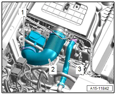
- Remove the air filter upper section. Refer to → Chapter "Air Filter Housing, Removing and Installing".
- Loosen the hose clamps -1- and remove the air duct pipe -2-.
 Note
Note
Ignore -3-.
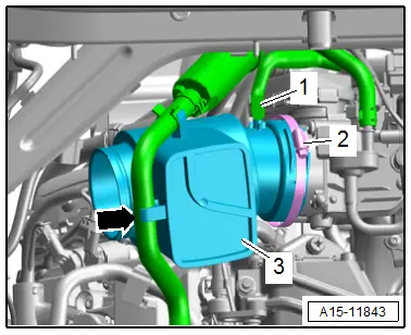
- Free up the hose -arrow- from the EVAP system on the resonator -3-.
- Remove the vacuum hose -1- from the resonator.
- Loosen the hose clamp -2- and remove the resonator.
- Remove the connector -1- for the Oxygen Sensor after Three Way Catalytic Converter -G130--2- from the bracket and disconnect it.
- Oxygen Sensor after Three Way Catalytic Converter -G130- with the Ring Wrench Set - Oxygen Sensor Probe Socket -3337/7-
 Note
Note
For better illustration, the installed position is shown with engine removed from behind.
Installing
Install in reverse order of removal and note the following:
 Note
Note
- Coat the new heated oxygen sensors with an assembly paste.
- When installing the previous oxygen sensor, coat the thread with hot bolt paste. Refer to the Parts Catalog.
- Assembly paste or hot bolt paste must not enter the slots on the sensor body.
- The wire for the heated oxygen sensor must always be secured back at the same positions when installing so that the heated oxygen sensor cable does not come in contact with the exhaust pipe.
- Install the air filter upper section. Refer to → Chapter "Air Filter Housing, Removing and Installing".
Tightening Specifications
- Refer to → Chapter "Overview - Heated Oxygen Sensor"
- Refer to → Chapter "Overview - Charge Air Hose Connections"
Heated Oxygen Sensor 2 -G108-/ Oxygen Sensor 2 after Catalytic Converter -G131-, Removing and Installing
Special tools and workshop equipment required
- Ring Wrench 7-Piece Set -3337-
Removing
 Note
Note
During installation, all cable ties must be installed at the same location.
- Remove the air filter housing. Refer to → Chapter "Air Filter Housing, Removing and Installing".
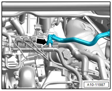
- Disconnect the vacuum connection -arrow- by pressing the release buttons on both sides.
- Remove the corresponding connector from the bracket, disconnect it and free up the wire.
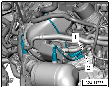
1 - For Heated Oxygen Sensor 2 -G108-
2 - For Oxygen Sensor 2 after Catalytic Converter -G131-
Heated Oxygen Sensor 2 -G108-
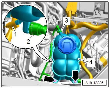
- Remove the bolts -arrows- and remove the coolant expansion tank -4- upward from the bracket.
- Disconnect the connector -1-.
- Move the coolant reservoir to the side with the hoses -2 and 3- still attached.
Continuation for Both Sides:
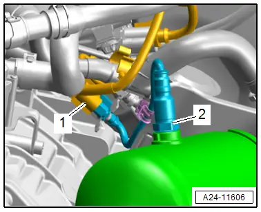
- Remove the respective heated oxygen sensor using the Ring Wrench Set - Oxygen Sensor Probe Socket -3337/7-:
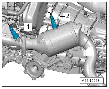
1 - Heated Oxygen Sensor 2 -G108-
2 - Oxygen Sensor 2 after Catalytic Converter -G131-
 Note
Note
For clarity, the installation position is shown with the engine removed.
Installing
Install in reverse order of removal and note the following:
 Note
Note
- Coat the new heated oxygen sensors with an assembly paste.
- When installing the previous oxygen sensor, coat the thread with hot bolt paste. Refer to the Parts Catalog.
- Assembly paste or hot bolt paste must not enter the slots on the sensor body.
- The wire for the heated oxygen sensor must always be secured back at the same positions when installing so that the heated oxygen sensor cable does not come in contact with the exhaust pipe.
- Install the air filter housing. Refer to → Chapter "Air Filter Housing, Removing and Installing".
Tightening Specifications
- Refer to → Chapter "Overview - Heated Oxygen Sensor"

