Audi Q7: Exhaust Pipes/Mufflers
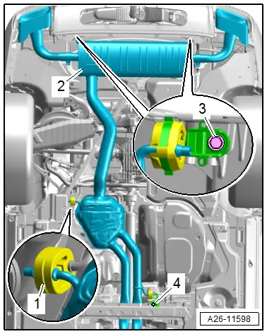
Overview - Muffler
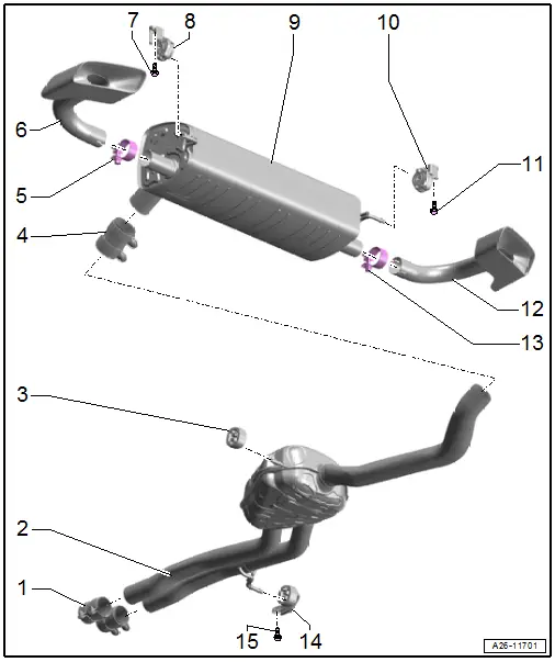
1 - Front Clamping Sleeves
- 30 Nm
- Installation position. Refer to → Fig. "Installed Position of Front Clamping Sleeves".
- Pushed all the way onto the front muffler
- Before tightening, align the exhaust system without tension. Refer to → Chapter "Exhaust System, Installing without Tension".
- Tighten threaded connections evenly.
2 - Center Muffler
- Original equipment as one unit with the rear muffler. If a repair is required replace each separately
- Separating point. Refer to → Chapter "Exhaust Pipes/Mufflers, Disconnecting".
- Exhaust System, Installing without Tension. Refer to → Chapter "Exhaust System, Installing without Tension".
3 - Retaining Loop
4 - Rear Clamping Sleeve
- 30 Nm
- For individual replacement of the center and rear mufflers
- Installation position. Refer to → Fig. "Installed Position of Rear Clamping Sleeve".
- Before tightening, align the exhaust system without tension. Refer to → Chapter "Exhaust System, Installing without Tension".
- Tighten threaded connections evenly.
5 - Screw-Type Clamp
- 60 Nm
6 - Left Tail Pipe
7 - Bolt
- 23 Nm
8 - Mount
- Replace if damaged
- Check the pretension. Refer to → Chapter "Exhaust System, Installing without Tension".
9 - Rear Muffler
- Original equipment as one unit with center muffler
- The center muffler and the rear muffler can be replaced individually if a repair is required.
- Separating point between the center and rear muffler. Refer to → Chapter "Exhaust Pipes/Mufflers, Disconnecting".
- Exhaust System, Installing without Tension. Refer to → Chapter "Exhaust System, Installing without Tension".
10 - Mount
- Replace if damaged
- Check the pretension. Refer to → Chapter "Exhaust System, Installing without Tension".
11 - Bolt
- 23 Nm
12 - Right Tail Pipe
13 - Screw-Type Clamp
- 60 Nm
14 - Mount
- Replace if damaged
- Check the pretension. Refer to → Chapter "Exhaust System, Installing without Tension".
15 - Bolt
- Tightening specification. Refer to → Body Exterior; Rep. Gr.66; Underbody Trim Panel; Overview - Tunnel Brace
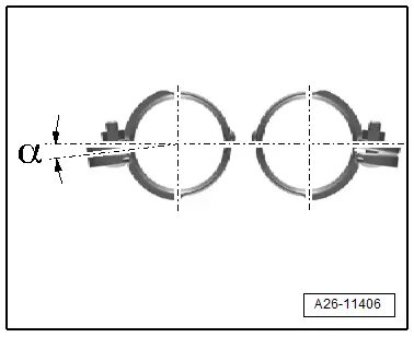
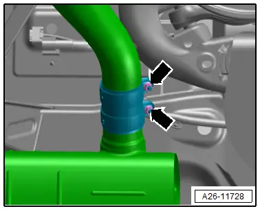
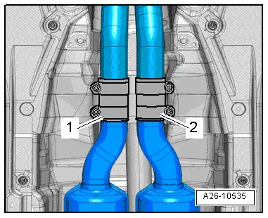
Installed Position of Front Clamping Sleeves
- Position the clamping sleeves in the center on the separating point.
- Installed position: the threaded connections face outward.
- Angle -α- = at least 20º.
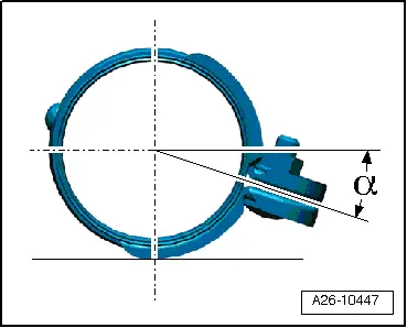
Installed Position of Rear Clamping Sleeve
- Position the clamping sleeve in the center on the separating point.
- Installation position: threaded connections to the right.
- Angle -α- = approximately 20º.
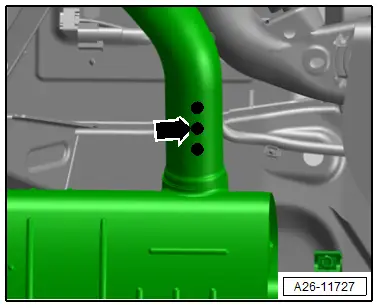
Exhaust Pipes/Mufflers, Disconnecting
- A separating point has been provided in the connecting pipe for individual replacement of the center or rear muffler.
- The separating point is marked by an indentation around the circumference of the exhaust pipe.
Special tools and workshop equipment required
- Chain Pipe Cutter -VAS6254-
Procedure
- Separate the exhaust pipes at a right angle at the separating point -arrow- using a Chain Pipe Cutter -VAS6254-.
- Position the clamping sleeve in the center ti the separation cut (refer to → Fig. "Installed Position of Rear Clamping Sleeve") and tighten the nuts -arrows-.
- Install the exhaust system without tension. Refer to → Chapter "Exhaust System, Installing without Tension".
Tightening Specifications
- Refer to → Chapter "Overview - Muffler"
Front Muffler, Removing and Installing
Removing
 Caution
This procedure contains mandatory replaceable parts. Refer to component overview prior to starting procedure.
Mandatory Replacement Parts
- Seals - Catalytic Converter
- Lock nuts - Front muffler
- Remove the rear noise insulation. Refer to → Body Exterior; Rep. Gr.66; Noise Insulation; Noise Insulation, Removing and Installing.
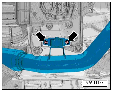
- Remove the nuts -arrows- from the corresponding front muffler.
 Caution
Risk of damaging the decoupling element inside the front exhaust pipe.
Do not bend decoupling element in the front muffler more than 10Âş.
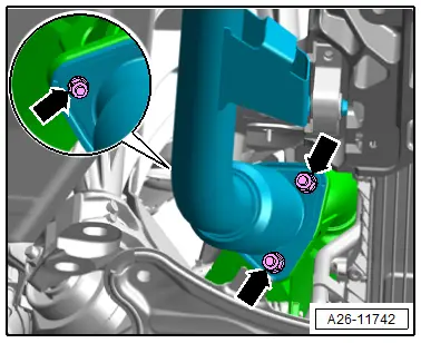
- Remove the bolts -arrows-.
- Loosen the clamping sleeves -1 or 2-, slide it back and remove the corresponding front muffler.

Installing
Install in reverse order of removal and note the following:
 Note
Note
Replace seals and self-locking nuts after disassembly.
- Install the exhaust system without tension. Refer to → Chapter "Exhaust System, Installing without Tension".
Tightening Specifications
- Refer to → Chapter "Overview - Muffler"
- Refer to → Body Exterior; Rep. Gr.66; Noise Insulation; Overview - Noise Insulation.
Muffler, Removing and Installing
Muffler with Center Muffler, Removing and Installing, Rear Muffler without Separating Point
Removing
- Remove the center underbody trim panel. Refer to → Body Exterior; Rep. Gr.66; Underbody Trim Panel; Underbody Trim Panels, Removing and Installing.
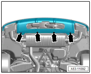
- Remove the bolts -arrows- on the rear diffuser.
- Loosen the front clamping sleeves -1 and 2--arrows- and slide them toward the rear.
- Slightly lower the front exhaust pipe and remove the clamping sleeves.
 WARNING
Risk of accident due to the weight of the muffler.
A second technician is needed to remove the rear muffler.
- Remove the left and right bolts -3- and disengage the retaining loop -1-.
- Remove the bolt -4- and the muffler -2-. While doing so, pay attention to the diffuser.
Installing
Install in reverse order of removal and note the following:
- Install the exhaust system without tension. Refer to → Chapter "Exhaust System, Installing without Tension".
Tightening Specifications
- Refer to → Chapter "Overview - Muffler"
- Refer to → Body Exterior; Rep. Gr.66; Underbody Trim Panel; Overview - Underbody Trim Panels.
- Refer to → Body Exterior; Rep. Gr.63; Rear Bumper; Overview - Bumper Cover.
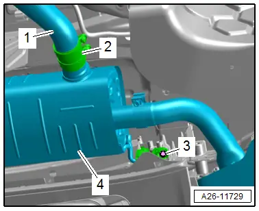
Muffler, Removing and Installing, Rear Muffler with Separating Point
Removing
- Loosen the clamping sleeve -2- and push it on the exhaust pipe.
- Remove the left and right bolts -3- and remove the muffler -4-.
- Tie up the exhaust pipe -1-.
Installing
Install in reverse order of removal and note the following:
- Install the exhaust system without tension. Refer to → Chapter "Exhaust System, Installing without Tension".
Tightening Specifications
- Refer to → Chapter "Overview - Muffler"
Exhaust System, Installing without Tension
Procedure
- Align the exhaust system when cold.
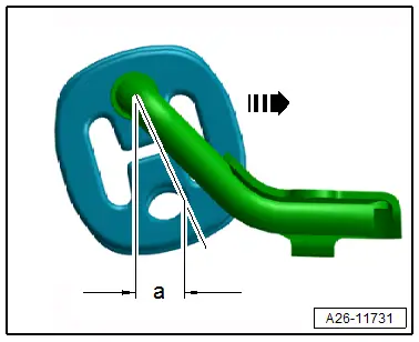
Exhaust System, Aligning
- Loosen the threaded connections on the front clamping sleeves.
- Push the exhaust system far enough forward in direction of -arrow- until the pre-load on the retaining loop at the exhaust pipe is -a- = 6 to 10 mm.
- Position the front clamping sleeves (refer to → Fig. "Installed Position of Front Clamping Sleeves") and tighten the threaded connections evenly.
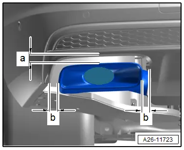
Tail Pipes, Aligning
- Check distance of left and right tail pipes to bumper:
- Dimension -a- 16 mm.
- Dimension -b- left = dimension -b- right.
Tightening Specifications
- Refer to → Chapter "Overview - Muffler"
Exhaust System, Checking for Leaks
- Start the engine and let it run at idle.
- Seal the tail pipes with cloths or plugs during the leakage test.
- Check for leaks by listening at connection areas at cylinder head and exhaust manifold, exhaust manifold and front exhaust pipe, etc.
- Repair the determined leaks.

