Audi Q7: Injection System
Component Location Overview - Injection System
Locations Engine Compartment
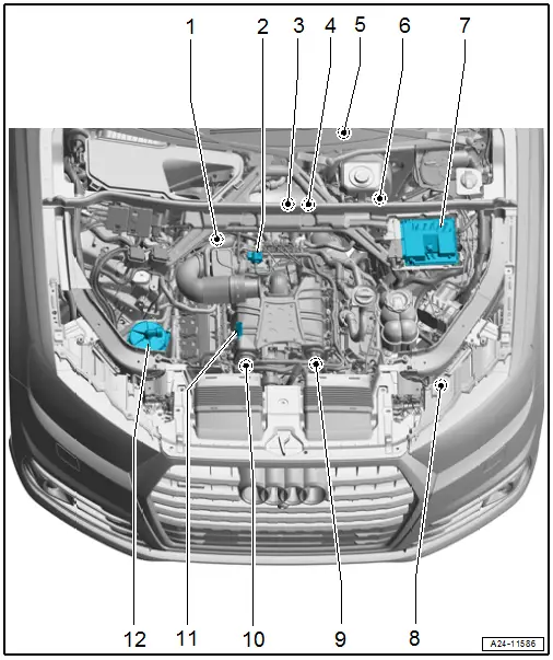
1 - Crankcase Ventilation Shut-Off Valve -N548-
2 - EVAP Canister Purge Regulator Valve 1 -N80-
3 - Coolant Recirculation Pump -V50-
- Component location. Refer to → Fig. " Coolant Recirculation Pump -V50- Component Location".
- Overview. Refer to → Chapter "Overview - Electric Coolant Pump".
4 - Transmission Fluid Cooling Valve -N509-
- Component location. Refer to → Fig. " Transmission Fluid Cooling Valve -N509- Component Location".
- Overview. Refer to → Chapter "Overview - Electric Coolant Pump".
5 - Accelerator Pedal Position Sensor -G79-/Accelerator Pedal Position Sensor 2 -G185-
- Component location. Refer to → Fig. " Accelerator Pedal Position Sensor -G79-/Accelerator Pedal Position Sensor 2 -G185- Component Location".
6 - Brake Lamp Switch -F-
- Component location. Refer to → Fig. " Brake Lamp Switch -F- Component Location".
7 - Engine Control Module -J623-
- Removing and installing. Refer to → Chapter "Engine Control Module -J623-, Removing and Installing".
8 - Charge Air Cooling Pump -V188-
- Component location. Refer to → Fig. " Charge Air Cooling Pump -V188- Component Location".
- Overview. Refer to → Chapter "Overview - Electric Coolant Pump".
9 - Intake Manifold Runner Position Sensor 2 -G512-
- Overview. Refer to → Chapter "Overview - Intake Manifold Lower Section with Fuel Rail".
10 - Intake Manifold Runner Position Sensor -G336-
- Overview. Refer to → Chapter "Overview - Intake Manifold Lower Section with Fuel Rail".
11 - Air Filter Bypass Door Valve -N275-
- Component location. Refer to → Fig. " Air Filter Bypass Door Valve -N275- Component Location".
12 - Secondary Air Injection Pump Motor -V101-
- Overview. Refer to → Chapter "Overview - Secondary Air Injection System".
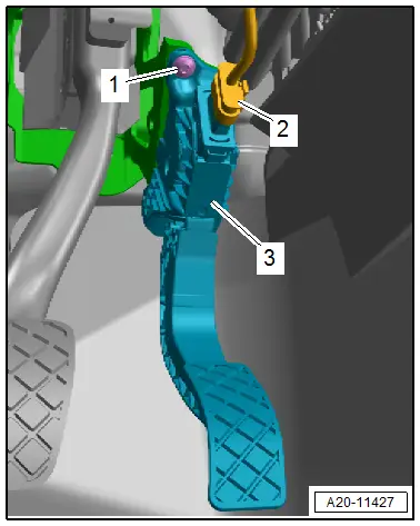
Accelerator Pedal Position Sensor -G79-/Accelerator Pedal Position Sensor 2 -G185- Component Location
- In the accelerator pedal module -3-.
 Note
Note
The Accelerator Pedal Position Sensor -G79- and the Accelerator Pedal Position Sensor 2 -G185- are part of the accelerator pedal module and cannot be replaced separately.
Removing and installing. Refer to → Fuel Supply - Gasoline Engines; Rep. Gr.20; Accelerator Mechanism; Accelerator Pedal Position Sensors G79/G185, Removing and Installing
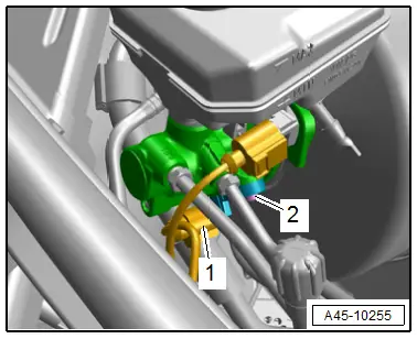
Brake Lamp Switch -F- Component Location
- In the engine compartment on the brake master cylinder.
1 - Connector for Brake Lamp Switch -F-
Removing and installing. Refer to → Brake System; Rep. Gr.45; Sensors; Brake Lamp Switch, Removing and Installing.
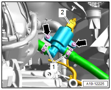
Engine Temperature Control Sensor -G694- Component Location
- -1- under the intake manifold lower section, cylinder bank 1 (right)
Removing and installing. Refer to → Chapter "Engine Temperature Control Temperature Sensor -G694-, Removing and Installing".
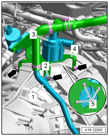
Coolant Recirculation Pump -V50- Component Location
- On the top of the transmission housing
3 - Coolant Recirculation Pump -V50-
Removing and installing. Refer to → Chapter "Coolant Recirculation Pump -V50-, Removing and Installing".
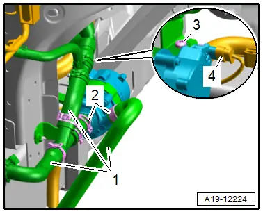
Charge Air Cooling Pump -V188- Component Location
- On the left front longitudinal member.
4 - Charge Air Cooling Pump -V188- Connector
Removing and installing. Refer to → Chapter "Charge Air Cooling Pump -V188-, Removing and Installing".
Transmission Fluid Cooling Valve -N509- Component Location
- On the top of the transmission housing
2 - Transmission Fluid Cooling Valve -N509-
Removing and installing. Refer to → Chapter "Coolant Valves, Removing and Installing".
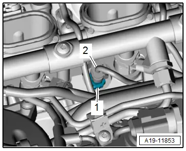
Air Filter Bypass Door Valve -N275- Component Location
- Right front on the air filter housing.
2 - Air Filter Bypass Door Valve -N275- Connector
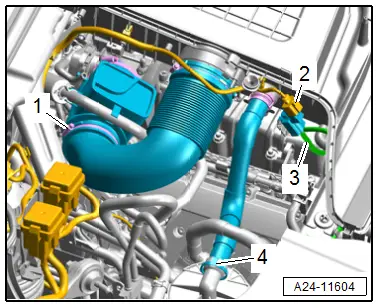
Installed Location, Engine from Above
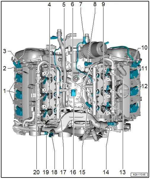
1 - Ignition Coil With Power Output Stage for Cylinder Bank 1
- Ignition Coil 1 with Power Output Stage -N70-
- Ignition Coil 2 with Power Output Stage -N127-
- Ignition Coil 3 with Power Output Stage -N291-
- Overview. Refer to → Chapter "Overview - Ignition System".
2 - Exhaust Camshaft Adjustment Valve 1 -N318-
- Overview. Refer to → Chapter "Overview - Valvetrain".
3 - Camshaft Adjustment Valve 1 -N205-
- Overview. Refer to → Chapter "Overview - Valvetrain".
4 - FSI Fuel Injector
- Cylinder 1 Fuel Injector -N30-
- Cylinder 2 Fuel Injector -N31-
- Cylinder 3 Fuel Injector -N32-
- Overview. Refer to → Chapter "Overview - Fuel Rail with Fuel Injectors".
5 - Knock Sensor 1 -G61-
- Overview. Refer to → Chapter "Overview - Ignition System".
6 - Knock Sensor 2 -G66-
- Overview. Refer to → Chapter "Overview - Ignition System".
7 - Oil Pressure Switch -F22-
- Overview. Refer to → Chapter "Overview - Oil Filter".
8 - Reduced Oil Pressure Switch -F378-
- Overview. Refer to → Chapter "Overview - Oil Filter".
9 - FSI Fuel Injector
- Cylinder 4 Fuel Injector -N33-
- Cylinder 5 Fuel Injector -N83-
- Cylinder 6 Fuel Injector -N84-
- Overview. Refer to → Chapter "Overview - Fuel Rail with Fuel Injectors".
10 - Camshaft Adjustment Valve 2 -N208-
- Overview. Refer to → Chapter "Overview - Valvetrain".
11 - Exhaust Camshaft Adjustment Valve 2 -N319-
- Overview. Refer to → Chapter "Overview - Valvetrain".
12 - Ignition Coil With Power Output Stage for Cylinder Bank 2
- Ignition Coil 4 with Power Output Stage -N292-
- Ignition Coil 5 with Power Output Stage -N323-
- Ignition Coil 6 with Power Output Stage -N324-
- Overview. Refer to → Chapter "Overview - Ignition System".
13 - MPI Fuel Injector
- Cylinder 4 Fuel Injector 2 -N535-
- Cylinder 5 Fuel Injector 2 -N536-
- Cylinder 6 Fuel Injector 2 -N537-
- Overview. Refer to → Chapter "Overview - Intake Manifold Lower Section with Fuel Rail".
14 - Camshaft Position Sensor 2 -G163-
- Overview. Refer to → Chapter "Overview - Ignition System".
15 - Fuel Pressure Sensor -G247-
- Overview. Refer to → Chapter "Overview - Fuel Rail with Fuel Injectors".
16 - Low Fuel Pressure Sensor -G410-
17 - Engine Temperature Control Sensor -G694-
- Component location. Refer to → Fig. " Engine Temperature Control Sensor -G694- Component Location".
18 - Engine Coolant Temperature Sensor -G62-
- Overview. Refer to → Chapter "Overview - Engine Coolant Temperature Sensor".
19 - Camshaft Position Sensor -G40-
- Overview. Refer to → Chapter "Overview - Ignition System".
20 - MPI Fuel Injector
- Cylinder 1 Fuel Injector 2 -N532-
- Cylinder 2 Fuel Injector 2 -N533-
- Cylinder 3 Fuel Injector 2 -N534-
- Overview. Refer to → Chapter "Overview - Intake Manifold Lower Section with Fuel Rail".
Installed Location, Engine from Left
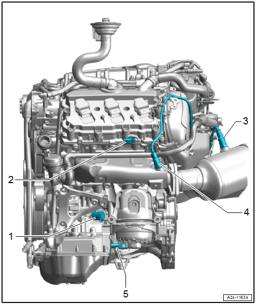
1 - Oil Pressure Regulation Valve -N428-
- Overview. Refer to → Chapter "Overview - Oil Pressure Switch/Oil Pressure Regulation Valve".
2 - Camshaft Position Sensor 4 -G301-
- Overview. Refer to → Chapter "Overview - Ignition System".
3 - Oxygen Sensor 2 after Catalytic Converter -G131-
- With Heater for Oxygen Sensor 2 after Catalytic Converter -Z30-
- Overview. Refer to → Chapter "Overview - Heated Oxygen Sensor".
4 - Heated Oxygen Sensor 2 -G108-
- With Oxygen Sensor 2 Heater -Z28-
- Overview. Refer to → Chapter "Overview - Heated Oxygen Sensor".
5 - Left Electrohydraulic Engine Mount Solenoid Valve -N144-
Installed Locations, Engine from Right
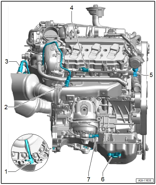
1 - Engine Speed Sensor -G28-
- Overview. Refer to → Chapter "Overview - Ignition System".
2 - Heated Oxygen Sensor -G39-
- With Oxygen Sensor Heater -Z19-
- Overview. Refer to → Chapter "Overview - Heated Oxygen Sensor".
3 - Oxygen Sensor after Catalytic Converter -G130-
- With Heater For Oxygen Sensor 1 after Catalytic Converter -Z30-
- Overview. Refer to → Chapter "Overview - Heated Oxygen Sensor".
4 - Camshaft Position Sensor 3 -G300-
- Overview. Refer to → Chapter "Overview - Ignition System".
5 - Fuel Metering Valve -N290-
- Overview. Refer to → Chapter "Overview - High Pressure Pump".
6 - Oil Level Thermal Sensor -G266-
- Overview. Refer to → Chapter "Overview - Oil Pan/Oil Pump".
7 - Right Electrohydraulic Engine Mount Solenoid Valve -N145-
Supercharger Component Location
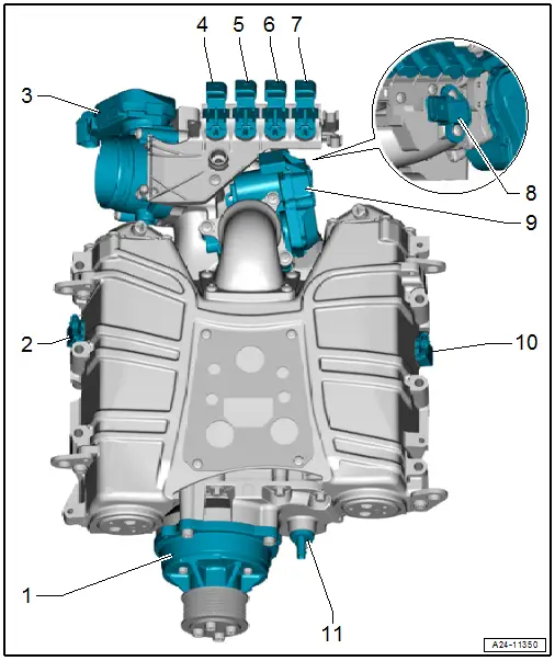
1 - Compressor Magnetic Clutch -N421-
- Refer to → Chapter "Overview - Supercharger"
2 - Charge Air Pressure Sensor -G31-/Intake Manifold Temperature Sensor -G72-
- Refer to → Chapter "Overview - Supercharger"
3 - Throttle Valve Control Module -J338-
- With EPC Throttle Drive -G186-, EPC Throttle Drive Angle Sensor 1 -G187- and EPC Throttle Drive Angle Sensor 2 -G188-
- Overview. Refer to → Chapter "Overview - Supercharger".
4 - Cooling Circuit Solenoid Valve -N492-
5 - Cylinder Head Coolant Valve -N489-
6 - Intake Manifold Runner Control Valve -N316-
7 - Secondary Air Injection Solenoid Valve -N112-
8 - Intake Air Temperature Sensor -G42-/Manifold Absolute Pressure Sensor -G71-
- Overview. Refer to → Chapter "Overview - Supercharger".
9 - Regulating Flap Control Unit -J808-
- With Regulating Flap Adjustment Motor -V380- and Regulating Flap Position Sensor -G584-
10 - Charge Air Pressure Sensor 2 -G447-/Intake Manifold Temperature Sensor 2 -G430-
- Overview. Refer to → Chapter "Overview - Supercharger".
11 - Turbocharger Speed Sensor 1 -G688-
Fuel System Leak Test
- Let the engine run a few minutes at a moderate RPM.
- Switch off the ignition.
- Check the entire fuel system for leaks.
- Replace the affected component if there are leaks in spite of correct tightening specifications.
- Perform a road test and fully depress the accelerator pedal at least one time.
- Check the high pressure area again for leaks.

