Audi Q7: Intake Manifold
Overview - Intake Manifold Lower Section with Fuel Rail
MPI Low Pressure Fuel Injection
 Note
Note
The components for cylinder bank 2 (left) are shown in the illustration.
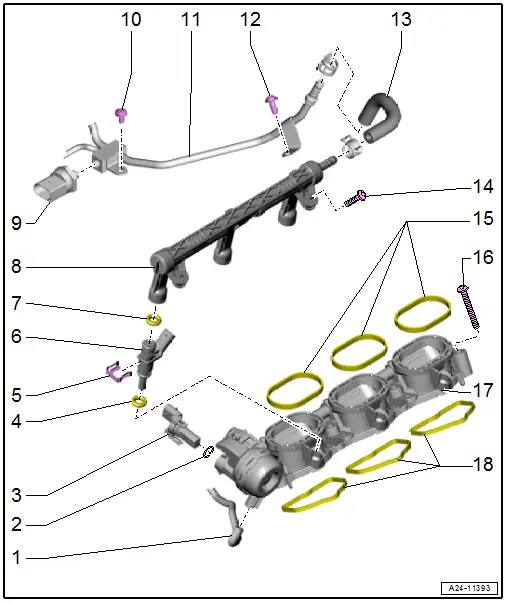
1 - Vacuum Hose
- To the Intake Manifold Runner Control Valve -N316-
2 - O-Ring
- Replace after removing
3 - Intake Manifold Runner Position Sensor 2 -G512-
- Cylinder bank 1 (right) Intake Manifold Runner Position Sensor -G336-
4 - O-Ring
- Replace after removing
5 - Clip
6 - Fuel Injector
- For MPI Low Pressure Fuel Injection
- Removing and installing. Refer to → Chapter "Fuel Injectors, Removing and Installing, FSI Fuel Injection".
7 - O-Ring
- Replace after removing
8 - Fuel Rail
- For MPI Low Pressure Fuel Injection
- Removing and installing. Refer to → Chapter "Intake Manifold Lower Section with Fuel Rail, Removing and Installing".
9 - Low Fuel Pressure Sensor -G410-
- 15 Nm
- Removing and installing. Refer to → Chapter "Low Fuel Pressure Sensor -G410-, Removing and Installing".
10 - Bolt
- 9 Nm
11 - Fuel Supply Line
- For MPI Low Pressure Fuel Injection
12 - Bolt
- 9 Nm
13 - Fuel Hose
14 - Bolt
- 5 Nm
15 - Seals
- Replace after removing
16 - Bolt
- Tightening specification. Refer to → Fig. "Intake Manifold Lower Section Cylinder Bank 1 (Right) - Tightening Specification" and → Fig. "Intake Manifold Lower Section Cylinder Bank 2 (Left) - Tightening Specification".
17 - Intake Manifold Lower Section
- Removing and installing. Refer to → Chapter "Intake Manifold Lower Section with Fuel Rail, Removing and Installing".
18 - Seals
- Replace after removing
Intake Manifold Lower Section Cylinder Bank 1 (Right) - Tightening Specification
- Tighten the bolts and nuts -arrows- in stages to 9 Nm.
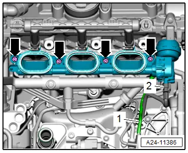
Intake Manifold Lower Section Cylinder Bank 2 (Left) - Tightening Specification
- Tighten the bolts and nuts -arrows- in stages to 9 Nm.

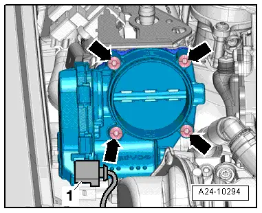
Throttle Valve Control Module -J338- - Tightening Specification
- Tighten the bolts -arrows- to 10 Nm in a diagonal sequence.

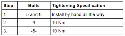
Regulating Flap Control Unit -J808- - Tightening Specification and Sequence
- Tighten the bolts in stages as follows:
Intake Manifold Lower Section with Fuel Rail, Removing and Installing
Special tools and workshop equipment required
- Torque Wrench 1331 Insert - Ring Wrench - 11mm & 17mm -VAG1331/2-
- Hand Vacuum Pump -VAS6213-
 Caution
This procedure contains mandatory replaceable parts. Refer to component overview prior to starting procedure.
Mandatory Replacement Parts
- Seals, top - Intake manifold lower section
- Seals, bottom - Intake manifold lower section
Removing
- Remove the supercharger. Refer to → Chapter "Supercharger, Removing and Installing".
Intake Manifold Lower Section Cylinder Bank 1 (Right):
- Free up the fuel hose -1- from the MPI fuel rail.
- Disconnect the connectors -4- and free up the wires:
 WARNING
The fuel system is under pressure.
Risk of injury from fuel spraying out.
- Wear protective eyewear.
- Wear safety gloves.
- Reduce the pressure: place clean cloths around the connection point and carefully open the connection point.
- Loosen the clamp -2- and remove the fuel hose.
- Remove the bolts -3 and arrow-.
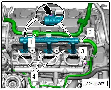
- Disconnect the vacuum hose -2-.
- Remove the bolts -arrows- and the right intake manifold lower section while doing so be careful of the MPI fuel line -3-.
- Disconnect the connector -1-.
Intake Manifold Lower Section Cylinder Bank 2 (Left):
- Free up the vacuum hoses on the fuel rail for the MPI system.
 WARNING
The fuel system is under pressure.
Risk of injury from fuel spraying out.
- Wear protective eyewear.
- Wear safety gloves.
- Reduce the pressure: place clean cloths around the connection point and carefully open the connection point.
- Loosen the clamp -2- and remove the fuel hose.
- Disconnect the connectors -3- and free up the wires.
- Remove the bolts -1 and arrows-.
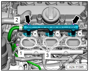
- Disconnect the connector -2- and the vacuum hose -1-.
- Remove the bolts -arrows- and the left intake manifold lower section while doing so be careful of the MPI fuel line.

Continuation for Both Sides:
 Caution
Risk of destroying the engine.
Cover the intake ducts with clean cloths to prevent small particles from getting into the engine through the intake ducts in the cylinder heads.
Installing
Install in reverse order of removal and note the following:
 Note
Note
Replacing the seals after removal.
 Caution
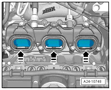
The intake manifold flaps could be damaged.
To prevent the intake manifold flaps from jamming with the baffles in the cylinder head, the flaps must be open all the way in direction of -arrow- when installing the intake manifold lower section.
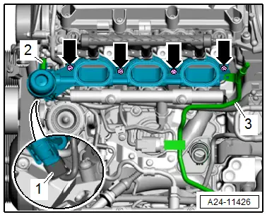
Intake Manifold Lower Section Cylinder Bank 1 (Right):
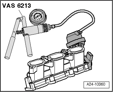
- Connect the Hand Vacuum Pump -VAS6213- to the right vacuum actuator connection, as illustrated.
- Produce a vacuum using the pump.
- The intake manifold flaps are opened.
Intake Manifold Lower Section Cylinder Bank 2 (Left):
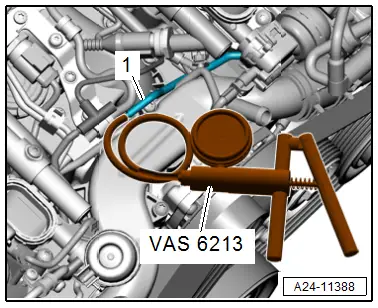
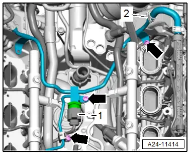
- Connect the Hand Vacuum Pump -VAS6213- to the vacuum hose -1- for the left vacuum actuator, as shown.
- Produce a vacuum using the pump.
- The intake manifold flaps are opened.
Continuation for Both Sides:
- Tighten the screws and nuts for the lower intake manifold section.
- Press the intake manifold lower section with the fuel rail evenly onto fuel injectors.
- Remove the hand vacuum pump from the vacuum actuator connection or the vacuum hose.
- Install the supercharger. Refer to → Chapter "Supercharger, Removing and Installing".
Tightening Specifications
- Refer to → Chapter "Overview - Intake Manifold Lower Section with Fuel Rail"
- Refer to → Fig. "Intake Manifold Lower Section Cylinder Bank 2 (Left) - Tightening Specification"
- Refer to → Fig. "Intake Manifold Lower Section Cylinder Bank 1 (Right) - Tightening Specification"
Throttle Valve Control Module -J338-, Removing and Installing
 Caution
This procedure contains mandatory replaceable parts. Refer to component overview prior to starting procedure.
Mandatory Replacement Parts
- O-rings - Intermediate flange
Removing
- Remove the engine cover. Refer to → Chapter "Engine Cover, Removing and Installing".
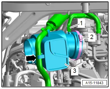
- Free up the hose -arrow- from the EVAP system on the resonator -3-.
- Remove the vacuum hose -1- from the resonator.
- Loosen the hose clamp -2- and remove the resonator.
- Disconnect the connector -1-.
- Remove the bolts -arrows- and the Throttle Valve Control Module - J338-.
- Remove the intermediate flange from the Crankcase Ventilation Shut-Off Valve -N548-.
 Caution
Risk of destroying the engine.
Cover the intake channel with a clean cloth to prevent small particles from getting into the compressor.
Installing
Install in reverse order of removal and note the following:
 Note
Note
- Replace the O-rings after removing them.
- Secure all hose connections with hose clamps that match the ones used in series production. Refer to the Parts Catalog.
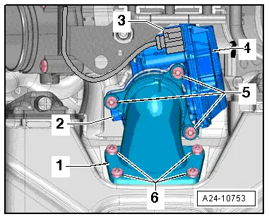
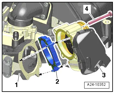
- Insert the intermediate flange -2- with the O-rings into the supercharger -1--left arrows-.
- Position the Throttle Valve Control Module -J338--3- onto the intermediate flange -right arrows-.
- Tighten the bolts -4-.
- Engage the Crankcase Ventilation Shut-Off Valve -N548-.
- Install the engine cover. Refer to → Chapter "Engine Cover, Removing and Installing".
Adapt the throttle valve control module after replacing.
- Connect the Vehicle Diagnostic Tester.
- Switch the ignition on.
- Select and start the Diagnostic operating mode.
- Select the Test plan tab.
- Select the button Individual tests and select the following tree structures one after the other:
- Drivetrain
- TFSI V6
- 01 - OBD-capable systems
- Simos Fuel Injection and Ignition
- Functions
- Adapt the throttle valve control module.
Tightening Specifications
- Refer to → Fig. " Throttle Valve Control Module -J338- - Tightening Specification"
- Refer to → Chapter "Overview - Charge Air Hose Connections"
Regulating Flap Control Unit -J808-, Removing and Installing
 Caution
This procedure contains mandatory replaceable parts. Refer to component overview prior to starting procedure.
Mandatory Replacement Parts
- O-rings - Intermediate flange
- O-rings - Bypass connection
Removing
- Remove the engine cover. Refer to → Chapter "Engine Cover, Removing and Installing".
- Disconnect the connector -3-.
- Remove the bolts -5 and 6-.
- Remove the bypass connection -1- with the intermediate flange -2- and Regulating Flap Control Unit -J808--4-.

Installing
Install in reverse order of removal and note the following:
 Note
Note
Replace the O-rings after removing them.
- Install the engine cover. Refer to → Chapter "Engine Cover, Removing and Installing".
Adapt the regulating flap control unit after replacing.
- Connect the Vehicle Diagnostic Tester.
- Switch the ignition on.
- Select and start the Diagnostic operating mode.
- Select the Test plan tab.
- Select the button Individual tests and select the following tree structures one after the other:
- Drivetrain
- TFSI V6
- 01 - OBD-capable systems
- Simos Fuel Injection and Ignition
- Functions
- Adapt the regulating flap control unit.
Tightening Specifications
- Refer to → Fig. " Regulating Flap Control Unit -J808- - Tightening Specification and Sequence"
Fuel Line, Removing and Installing
Removing
- Remove the cylinder bank 1 (right) intake manifold lower section. Refer to → Chapter "Intake Manifold Lower Section with Fuel Rail, Removing and Installing".
- Remove the bolts -2 and 3- and connection -1-.
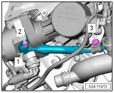
- Loosen the clamp -2- and remove the fuel hose.
- Remove bolts -arrows-, remove the fuel line and disconnect connector -1-.
Installing
Install in reverse order of removal and note the following:
- Install the cylinder bank 1 (right) intake manifold lower section. Refer to → Chapter "Intake Manifold Lower Section with Fuel Rail, Removing and Installing".
Tightening Specifications
- Refer to → Chapter "Overview - Intake Manifold Lower Section with Fuel Rail"

