Audi Q7: Mobile Online Services
Overview - Mobile Online Services
The mobile online service (1W3) consist of the eCall, connected Gateway, and the DataBuson Board Diagnostic Interface -J533-.
The DataBuson Board Diagnostic Interface -J533- is installed under the driver seat for crash safety. The DataBuson Board Diagnostic Interface -J533- contains an emergency module and a compass module. A separate SIM card is installed for the emergency call function and roadside assistance.
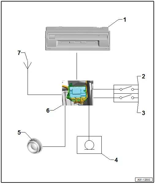
1 - Information Electronics Control Module 1 -J794- in the glove compartment
2 - Roadside Assistance Button -E275- in the Front Interior Lamp -W1-
3 - Emergency Call Button -E276- in the Front Interior Lamp -W1-
4 - Left Front Microphone -R140- in the Front Interior Lamp -W1-
5 - Emergency Call Module Speaker -R335- in the driver side instrument panel cover
6 - DataBuson Board Diagnostic Interface -J533- under the driver seat
7 - GPS Antenna -R50- in the Roof Antenna -R216-
- Not on navigation, 7UG/7UH
- Emergency Module Antenna -R263- under the front instrument panel
Troubleshooting
The mobile online services system is capable of self-diagnosis (OBD).
Fault Finding is performed using the "Guided Fault Finding" on the Vehicle Diagnostic Tester.
When there are concerns about the function, it necessary to be familiar with the Mobile Online Services functions.
For additional information. Refer to the Owner's Manual and → Wiring diagrams, Troubleshooting & Component locations.
Component Location Overview - Mobile Online Services
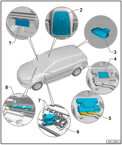
1 - Information Electronics Control Module 1 -J794-
- Connector Assignment. Refer to → Wiring diagrams, Troubleshooting & Component locations.
- Removing and Installing. Refer to → Chapter "Information Electronics Control Module 1 -J794-, Removing and Installing".
2 - Front Interior Lamp -W1-
- With Roadside Assistance Button -E275-/Emergency Call Button - E276-/Left Front Microphone -R140-
- Removing and installing. Refer to → Electrical Equipment; Rep. Gr.96; Controls; Front Interior Lamp/Reading Lamp, Removing and Installing.
3 - GPS Antenna -R50-
- In the Roof Antenna -R216-
- Not on navigation, 7UG/7UH
4 - Telematics Emergency Battery -A16-
- With DataBuson Board Diagnostic Interface -J533-
- Removing and Installing. Refer to Maintenance.
5 - DataBuson Board Diagnostic Interface -J533-
- Connector Assignment. Refer to → Wiring diagrams, Troubleshooting & Component locations.
- Removing and installing. Refer to → Electrical Equipment; Rep. Gr.97; Control Modules; Data Bus on Board Diagnostic Interface J533, Removing and Installing.
6 - Emergency Call Module Speaker -R335-
- Removing and Installing. Refer to → Chapter "Emergency Call Module Speaker -R335-, Removing and Installing".
7 - Bolt
- 2 Nm
- Quantity: 2
8 - Emergency Module Antenna -R263-
- Removing and Installing. Refer to → Chapter "Emergency Module Antenna, Removing and Installing".
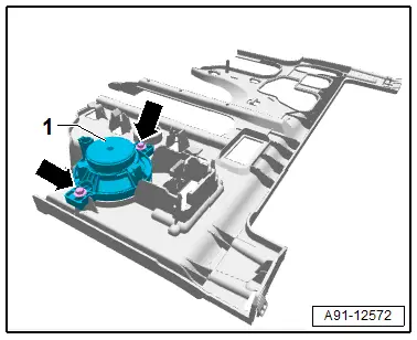
Emergency Call Module Speaker -R335-, Removing and Installing
The Emergency Call Module Speaker -R335- is located in the driver side instrument panel cover.
Removing
- Turn off the ignition and all electrical equipment and remove the ignition key.
- Remove the instrument panel cover on the driver side. Refer to → Body Interior; Rep. Gr.68; Storage Compartments and Covers; Overview - Driver Side Instrument Panel Cover.
- Release and disconnect the connectors on the Emergency Call Module Speaker -R335-.
- Remove the bolts -arrows- on the Emergency Call Module Speaker -R335--1-.
- Remove the Emergency Call Module Speaker -R335--1- from the instrument panel cover.
Installing
- Install in reverse order of removal.
Tightening Specifications
- Refer to → Chapter "Component Location Overview - Mobile Online Services"
Special Tools
Special tools and workshop equipment required
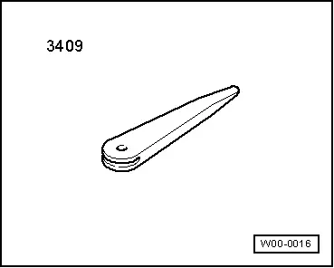
- Trim Removal Wedge -3409-
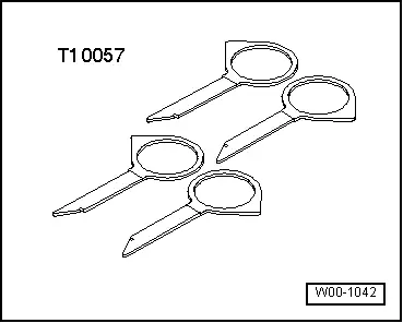
- Radio Removal Tool -T10057-
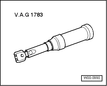
- Torque Wrench 1783 - 2-10Nm -VAG1783-
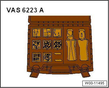
- Fiber-Optic Repair Set - Connector Protective Caps -VAS6223/9-.
- Calibration Unit -VAS6350A-
- Calibration System -VAS721001-
- Vehicle Diagnostic Tester
Revision History
DRUCK NUMBER: A005A009321