Audi Q7: Overview - Front Seat
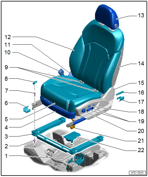
1 - Connector Station
- Connector assignment. Refer to → Wiring diagrams, Troubleshooting & Component locations.
2 - Clip
- Quantity: 4
3 - Front Seat Mount
- Under the carpet
- Clipped in the vehicle floor
4 - Seat Trim in Front
- Overview. Refer to → Chapter "Overview - Seat Pan, Trim Panels".
5 - Seat Pan
- Overview. Refer to → Chapter "Overview - Seat Pan".
6 - Front Cover
- For the seat rail
- Overview. Refer to → Chapter "Overview - Seat Pan, Trim Panels".
7 - Bolt
- 50 Nm
- Quantity: 4
- Front seat, removing and installing. Refer to → Chapter "Front Seat, Removing and Installing".
8 - Front Spindle Cover
- Overview. Refer to → Chapter "Overview - Seat Pan, Trim Panels".
9 - Child Seat Anchor
- For the front passenger seat only
- Overview. Refer to → Chapter "Overview - Front Child Seat Anchors".
10 - Front Seat Belt Latch
- Overview. Refer to → Chapter "Overview - Front Seat Belt Latch".
11 - Tunnel Side Seat Side Trim
- Overview. Refer to → Chapter "Overview - Seat Pan, Trim Panels".
12 - Backrest
- Overview. Refer to → Chapter "Overview - Front Backrest".
13 - Headrest
- Overview. Refer to → Chapter "Overview - Headrest".
14 - Backrest Cover
- Overview. Refer to → Chapter "Overview - Front Backrest".
15 - Seat Side Trim on Side Sill
- Overview. Refer to → Chapter "Overview - Seat Pan, Trim Panels".
16 - Spindle Rear Cover
- Overview. Refer to → Chapter "Overview - Seat Pan, Trim Panels".
17 - Rear Cover
- For the seat rail
- Overview. Refer to → Chapter "Overview - Seat Pan, Trim Panels".
18 - Driver Side Massage Function Button -E670-
- Equipped on some models
- Front passenger side: Front Passenger Massage Function Button -E671-
- Overview. Refer to → Chapter "Overview - Seat Pan, Power Seat Adjustment Actuator/Switch".
19 - Driver Seat Adjustment Control Head -E470-
- Equipped on some models
- Front passenger side: Front Passenger Seat Adjustment Control Head -E471-
- Overview. Refer to → Chapter "Overview - Seat Pan, Power Seat Adjustment Actuator/Switch".
20 - Driver Seat Lumbar Support Adjustment Switch -E176-
- Equipped on some models
- Front passenger side Front Passenger Seat Lumbar Support Adjustment Switch -E177-
- Overview. Refer to → Chapter "Overview - Seat Pan, Power Seat Adjustment Actuator/Switch".
21 - Connector
- With a corrugated tube for the modular wiring routing
- Modular wiring routing, disconnecting and connecting. Refer to → Chapter "Modular Wiring Routing, Disconnecting and Connecting".
22 - Cover
- For the connector station
Overview - Front Backrest
Overview - Front Backrest, Lumbar Support
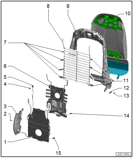
1 - Pneumatic Lumbar Support
- Module Carrier with Air Cushions for Lumbar Support
- Overview. Refer to → Chapter "Overview - Pneumatic System, Module Carrier/Lumbar Support/Seat Bolster Adjuster".
2 - Bolt
- Tightening specification. Refer to -item 7-.
3 - Backrest Bolster Inflation Adjuster
- Removing and Installing. Refer to → Chapter "Valve Block 1 in Driver Seat -N475-/ Valve Block 1 in Front Passenger Seat -N477- and Air Cushions, Removing and Installing".
4 - Expanding Clip
5 - Wire Frame
6 - Electro-Mechanical Lumbar Support
- Driver side: with Driver Seat Lumbar Support Curvature Adjustment Motor -V125-/ Driver Seat Lumbar Support Height Adjustment Motor -V129-
- Front passenger side: with Front Passenger Seat Lumbar Support Curvature Adjustment Motor -V126-/ Front Passenger Seat Lumbar Support Height Adjustment Motor -V130-
- Removing and Installing. Refer to → Chapter "Lumbar Support Adjustment Motors -V125-/-V126-/-V129-/-V130-, Removing and Installing".
7 - Tension Springs
- Note the different lengths
8 - Spring Mat
- For versions without lumbar support
- Removing and Installing. Refer to → Chapter "Spring Mat, Removing and Installing".
9 - Backrest
- Removing and Installing. Refer to → Chapter "Front Backrest, Removing and Installing".
10 - Backrest Cover
- Removing and Installing. Refer to → Chapter "Backrest Cover, Removing and Installing".
11 - Tension Springs
- Note the different lengths
12 - Threaded Plate
13 - Bolt
- 33 Nm
- Quantity: 4
- Self-locking
- Replace after removing
- Threaded holes for the bolts must be cleaned, for example, with a thread tap
14 - Rivet
15 - Bolt
- Tightening specification. Refer to -item 12-.
Overview - Front Backrest, Backrest Adjustment Motor
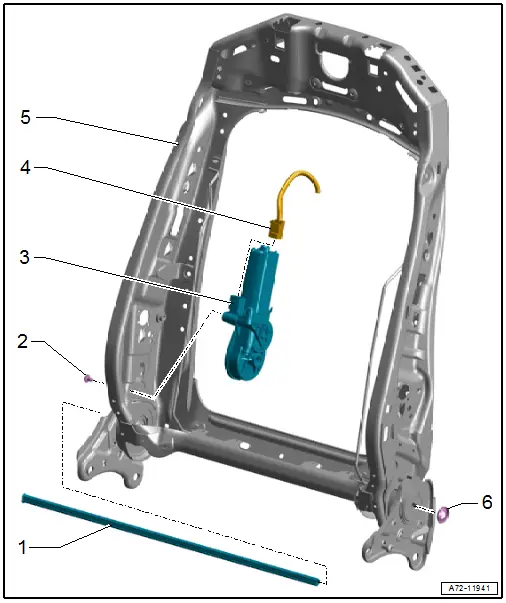
1 - Adjustment Shaft
2 - Bolt
- 7.5 Nm
3 - Driver Backrest Adjustment Motor -V45-
- Front passenger side: Front Passenger Backrest Adjustment Motor -V46-
- Removing and Installing. Refer to → Chapter "Driver and Front Passenger Backrest Adjustment Motor -V45-/-V46-, Removing and Installing".
4 - Connector
5 - Backrest Frame
6 - Lock Washer
- Replace after removing
- Push onto the adjustment shaft so that there is still at least 1.0 mm of play
Overview - Headrest
Overview - Headrest, with Height Adjustment
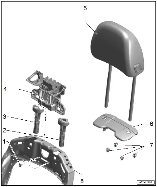
1 - Bolt
- 2.5 Nm
- Quantity: 2
2 - Left Headrest Guide
- With release ring
- Removing and installing. Refer to → Chapter "Headrest Guide, Removing and Installing, Headrest with Height Adjuster".
- Press until all three retainers are completely locked into the backrest frame
3 - Right Headrest Guide
- Removing and installing. Refer to → Chapter "Headrest Guide, Removing and Installing, Headrest with Height Adjuster".
- Press until all three retainers are completely locked into the backrest frame
4 - Cover
- For headrest
- Removing and installing. Refer to → Chapter "Headrest Guide, Removing and Installing, Headrest with Height Adjuster".
5 - Headrest
- Cannot be disassembled
- Removing and installing. Refer to → Chapter "Headrest, Removing and Installing, Headrest with Height Adjuster".
- Must be correctly locked in the headrest guides
6 - Trim
- For headrest
- Removing and installing. Refer to → Chapter "Headrest, Removing and Installing, Headrest with Height Adjuster".
7 - Clips
8 - Backrest Frame
Overview - Headrest, with Headrest and Angle Adjustment
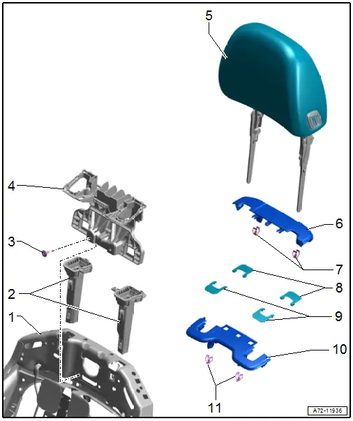
1 - Backrest Frame
2 - Headrest Guide
- Removing and installing. Refer to → Chapter "Headrest Guide, Removing and Installing, Headrest with Height and Angle Adjuster".
- Press until all three retainers are completely locked into the backrest frame
3 - Bolt
- 2.5 Nm
- Quantity: 2
4 - Cover
- For headrest
- Removing and installing. Refer to → Chapter "Headrest Guide, Removing and Installing, Headrest with Height and Angle Adjuster".
5 - Headrest
- Cannot be disassembled
- Removing and installing. Refer to → Chapter "Headrest, Removing and Installing, Headrest with Height and Angle Adjuster".
- Must be correctly locked in the headrest guides
6 - Rear Trim
- For headrest
- Removing and installing. Refer to → Chapter "Headrest, Removing and Installing, Headrest with Height and Angle Adjuster".
7 - Clips
8 - Rear Gap Covers
9 - Front Gap Covers
- With beveled corners
10 - Front Trim
- For headrest
- Removing and installing. Refer to → Chapter "Headrest, Removing and Installing, Headrest with Height and Angle Adjuster".
11 - Clips
