Audi Q7: Rear Axle Steering
Overview - Rear Axle Steering
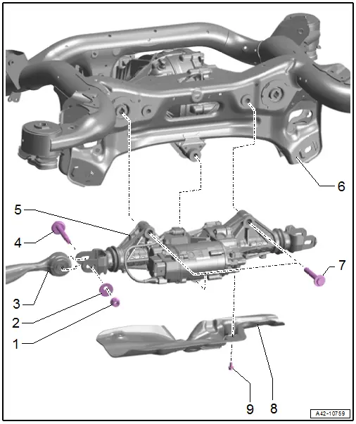
1 - Nut
- Tightening specification. Refer to -item 9-
2 - Eccentric Washer
3 - Tie Rod
- Removing and installing. Refer to → Chapter "Tie Rod, Removing and Installing".
4 - Bolt
- Replace after removing
5 - Rear Axle Steering Gear
- With integrated Rear Axle Steering Control Module -J1019-
- The Rear Axle Steering Control Module -J1019- cannot be replaced separately if faulty replace the rear axle.
- Removing and installing. Refer to → Chapter "Rear Axle Steering Gear, Removing and Installing".
6 - Subframe
7 - Bolt
- 90 Nm +180º
- Replace after removing
8 - Heat Shield
9 - Bolt
- 9 Nm
Rear Axle Steering Gear, Removing and Installing
Special tools and workshop equipment required
- Locking Tool -T40326-, not shown
 Caution
This procedure contains mandatory replaceable parts. Refer to component overview prior to starting procedure.
Mandatory Replacement Parts
- Nut and Bolt - Tie Rod to Rear Axle Steering
- Bolt - Rear Axle Steering to Subframe
Removing
Before starting work:
- Versions with coil springs: determine the curb weight position. Refer to → Chapter "Wheel Bearing in Curb Weight Position, Lifting Vehicles with Coil Spring".
- Versions with air suspension: determine the standard vehicle height. Refer to → Chapter "Wheel Bearing at Standard Vehicle Height, Lifting Vehicles with Air Suspension".
- Exhaust system without separating point: remove the rear muffler. Refer to → Rep. Gr.26; Exhaust Pipes/Mufflers; Overview - Muffler.
- Exhaust system with separating point: remove the exhaust pipe. Refer to → Rep. Gr.26; Exhaust Pipes/Mufflers; Overview - Muffler.
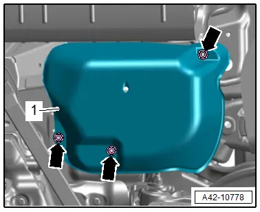
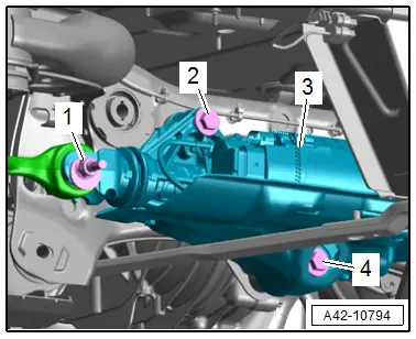
- Versions with air suspension: remove the nuts -arrows- and the cover -1- for the air supply unit.
- Release the safety catch in direction of -arrow-, push the retainer down and disconnect the connector from -3- from the Rear Axle Steering Control Module -J1019-.
- Disconnect the connector -2- on the Rear Axle Steering Control Module -J1019-.
 Note
Note
Ignore -1-.
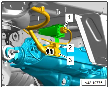
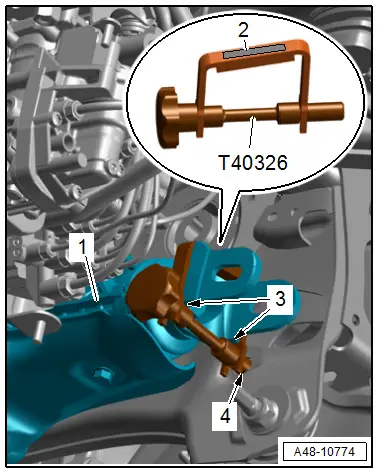
- Remove the left and right bolt -2- and disconnect the threaded connection -1-.
- Remove the bolt -4- and the rear axle steering -3-.
Installing
Install in reverse order of removal and note the following:
- Bring the rear axle steering into the installation position, install the Locking Tool - T40326-.

Right side of vehicle:
- Pay attention to the labeling -2-"rechts/right".
- The "arrow" points in the direction of travel.
- The rear axle steering -1- is positioned on the points -3- on the locking tool pin.
- The pin of the locking tool must engage in the holes -4- on the subframe.
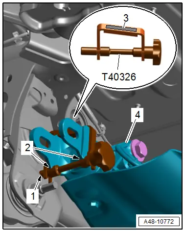
Left side of vehicle
- Pay attention to the labeling -3-"links/left".
- The "arrow" points in the direction of travel.
- The half round mounts -2- from the rear axle steering -4- must be positioned on the pin of the locking tool.
- The pin of the locking tool must engage in the holes -1- on the subframe.
- Tighten the threaded connections for the rear axle steering.
- Remove the Locking Tool -T40326-.
- Lifting the wheel bearing in curb weight position (refer to → Chapter "Wheel Bearing in Curb Weight Position, Lifting Vehicles with Coil Spring") or at standard vehicle height (refer to → Chapter "Wheel Bearing at Standard Vehicle Height, Lifting Vehicles with Air Suspension").
- Install the tie rods. Refer to → Chapter "Tie Rod, Removing and Installing".

 Note
Note
Pay attention to the procedures after installing the rear axle steering.
Procedures after Installing the Used Rear Axle Steering.
- After installing drive the vehicle on the alignment stand.
- Switch off the ignition when the vehicle has come to a stop. Only this way it can be ensured that the is in the straight-ahead position.
- Connect the Vehicle Diagnostic Tester.
- Switch the ignition on.
- Select and start the Diagnostic operating mode.
- Select the Test plan tab.
- Select the button Individual tests and select the following tree structures one after the other:
- Suspension
- Steering
- 01 - OBD-capable systems
- CB - Rear axle steering control module J1019
- CB - Rear axle steering control module functions
- CB - Basic setting
- Start the selected program and follow the instructions in the display of the Vehicle Diagnostic Tester.
- Then measure the vehicle. Refer to → Chapter "Vehicle Alignment".
Procedures after Installing a New Rear Axle Steering.
- Connect the Vehicle Diagnostic Tester.
- Switch the ignition on.
- Select and start the Diagnostic operating mode.
- Select the Test plan tab.
- Select the button Individual tests and select the following tree structures one after the other:
- Suspension
- Steering
- 01 - OBD-capable systems
- CB - Rear axle steering control module J1019
- CB - Rear axle steering control module functions
- CB - Replacing the control module
- Start the selected program and follow the instructions in the display of the Vehicle Diagnostic Tester.
- Drive the vehicle on the alignment stand.
- Switch off the ignition when the vehicle has come to a stop. Only this way it can be ensured that the is in the straight-ahead position.
- Connect the Vehicle Diagnostic Tester.
- Switch the ignition on.
- Select and start the Diagnostic operating mode.
- Select the Test plan tab.
- Select the button Individual tests and select the following tree structures one after the other:
- Suspension
- Steering
- 01 - OBD-capable systems
- CB - Rear axle steering control module J1019
- CB - Rear axle steering control module functions
- CB - Basic setting
- Start the selected program and follow the instructions in the display of the Vehicle Diagnostic Tester.
- Then measure the vehicle. Refer to → Chapter "Vehicle Alignment".
Tightening Specifications
- Refer to → Chapter "Overview - Rear Axle Steering"
- Refer to → Rep. Gr.26; Exhaust Pipes/Mufflers; Overview - Muffler.
- Refer to → Body Exterior; Rep. Gr.66; Underbody Trim Panel.
Rear Axle Steering Gear Orientation, Checking
Special tools and workshop equipment required
- Locking Tool -T40326-
Procedure
- Drive the vehicle on the hoist.
- Switch off the ignition when the vehicle has come to a stop. This is the only way to ensure that the rear axle steering is in the straight-ahead position.
The orientation of the rear axle steering is checked as follows:
- Install the Locking Tool -T40326-.
Right side of vehicle:
- Pay attention to the labeling -2-"rechts/right".
- The "arrow" points in the direction of travel.
- The rear axle steering -1- is positioned on the points -3- on the locking tool pin.
- The pin of the locking tool must engage in the holes -4- on the subframe.

Left side of vehicle
- Pay attention to the labeling -3-"links/left".
- The "arrow" points in the direction of travel.
- The half round mounts -2- from the rear axle steering -4- must be positioned on the pin of the locking tool.
- The pin of the locking tool must engage in the holes -1- on the subframe.
- If the Locking Tool -T40326- cannot be inserted as described, align the rear axle steering gear. Refer to → Chapter "Rear Axle Steering Gear, Aligning".

Rear Axle Steering Gear, Aligning
Special tools and workshop equipment required
- Locking Tool -T40326-
The rear axle steering must be aligned under the following conditions.
- If there are drivability problems.
- If there is high or uneven tire wear.
Procedure
- Versions with air suspension: remove the nuts -arrows- and the cover -1- for the air supply unit.

- Remove the left and right bolt -2- for the rear axle steering -3- and replace with new.
- Remove the bolt -4- and replace with new.
- Lightly install the bolts by hand.
 Note
Note
Ignore item -1-.
- Install the Locking Tool -T40326-.
Right side of vehicle:
- Pay attention to the labeling -2-"rechts/right".
- The "arrow" points in the direction of travel.
- The rear axle steering -1- is positioned on the points -3- on the locking tool pin.
- The pin of the locking tool must engage in the holes -4- on the subframe.

Left side of vehicle
- Pay attention to the labeling -3-"links/left".
- The "arrow" points in the direction of travel.
- The half round mounts -2- from the rear axle steering -4- must be positioned on the pin of the locking tool.
- The pin of the locking tool must engage in the holes -1- on the subframe.
- Tighten the threaded connections for the rear axle steering.
- Remove the Locking Tool -T40326-.
- After installing drive the vehicle on the alignment stand.
- Switch off the ignition when the vehicle has come to a stop. This is the only way to ensure that the rear axle steering is in the straight-ahead position.
- Connect the Vehicle Diagnostic Tester.
- Switch the ignition on.
- Select and start the Diagnostic operating mode.
- Select the Test plan tab.
- Select the button Individual tests and select the following tree structures one after the other:
- Suspension
- Steering
- 01 - OBD-capable systems
- CB - Rear axle steering control module J1019
- CB - Rear axle steering control module functions
- CB - Basic setting
- Start the selected program and follow the instructions in the display of the Vehicle Diagnostic Tester.
- Then measure the vehicle. Refer to → Chapter "Vehicle Alignment".
Tightening Specifications
- Refer to → Chapter "Overview - Rear Axle Steering"
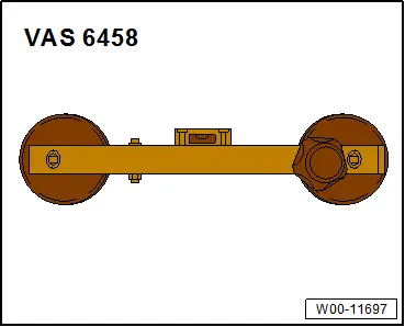
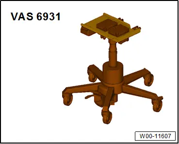
Special Tools
Special tools and workshop equipment required
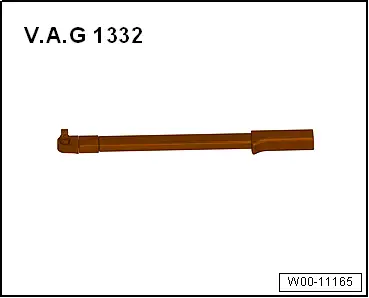
- Torque Wrench 1331 5-50Nm -VAG1331-
- Torque Wrench 1332 40-200Nm -VAG1332-
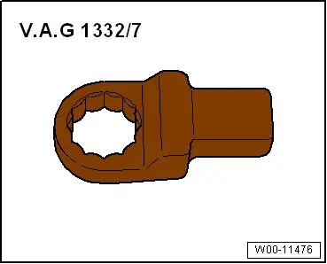
- Torque Wrench 1332 Insert - Ring Wrench - 21mm -VAG1332/7-
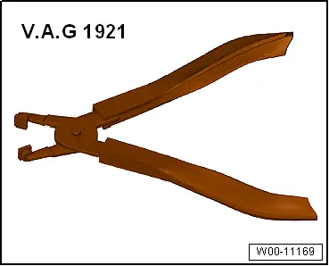
- Hose Clip Pliers -VAG1921-
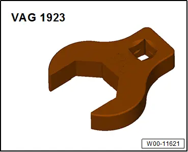
- Torque Wrench Insert - Open Jaw -VAG1923-
- Steering Wheel Scales -VAS6458-
- Engine and Gearbox Jack -VAS6931-
- Not illustrated:
- Locking Tool -T40326-
- Ball Joint Splitter -VAS251805-,
Revision History
DRUCK NUMBER: A005A010721