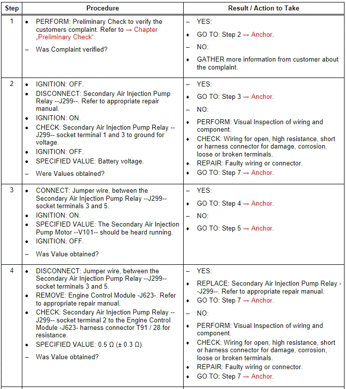
Audi Q7: Secondary Air Injection Pump Relay - J299- / Secondary Air Injection Pump Motor - V101-, Checking
General Description
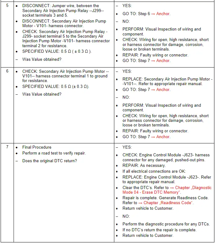
The secondary air injection system sends air into the exhaust using passages in the cylinder head. This extra air injection takes place using the Secondary Air Injection Pump Motor -V101- that is powered by the Secondary Air Injection Pump Relay -J299- on a cold-start of the engine for about 45 - 100 s and serves to quickly heat the catalytic converter(s) for improved emissions.
Special tools and workshop equipment required
- Multimeter.
- Wiring Diagram.
- Scan Tool.
Test requirements
- Fuses OK.
- Battery voltage OK.
- Switch OFF all electrical and electronic accessories.
- Vehicles with automatic transmission, ensure the selector lever position is in "P".
- Vehicles with manual transmission, ensure the shifter lever position is in "N" with the parking brake applied.
- Coolant temperature: ≥ 80º C.
- Observe all safety precautions: → Chapter "Safety Precautions".
- View clean working conditions: → Chapter "Clean Working Conditions".
- For Hybrid vehicles, refer to: → Chapter "High Voltage System General Warnings".
Test Procedure
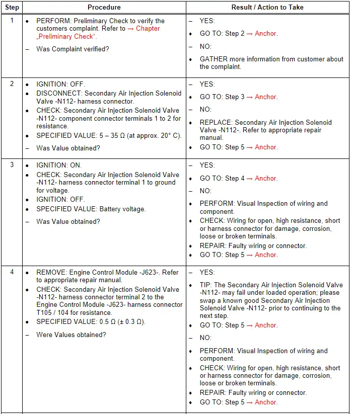
Secondary Air Injection Solenoid Valve - N112-, Checking
General Description
The secondary air injection system sends air into the exhaust, behind the exhaust valves, using a passage in the cylinder head. This extra air injection takes place on a cold-start of the engine for about 45 - 100 s and serves to quickly heat the catalytic converter(s) for improved emissions. A "pressure based secondary air diagnostics" function is used. In this system, the Engine Control Module -J623- controls the Secondary Air Injection Solenoid Valve -N112-, which allows the correct amount of air to be injected. The injected air quantity is determined from the pressure level.
Special tools and workshop equipment required
- Multimeter.
- Wiring Diagram.
- Scan Tool.
Test requirements
- Fuses OK.
- Battery voltage OK.
- Switch OFF all electrical and electronic accessories.
- Vehicles with automatic transmission, ensure the selector lever position is in "P".
- Vehicles with manual transmission, ensure the shifter lever position is in "N" with the parking brake applied.
- Coolant temperature: ≥ 80º C.
- Observe all safety precautions: → Chapter "Safety Precautions".
- View clean working conditions: → Chapter "Clean Working Conditions".
- For Hybrid vehicles, refer to: → Chapter "High Voltage System General Warnings".
Test Procedure
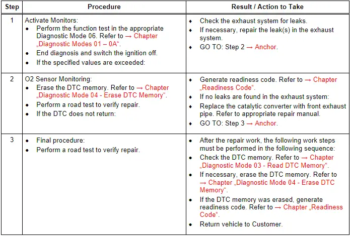
Three Way Catalytic Converter (TWC), Checking
General Description
A catalytic converter is a vehicle emissions control device that converts toxic pollutants in exhaust gas to less toxic pollutants by catalyzing a redox reaction (oxidation or reduction). Catalytic converters are used in internal combustion engines.
General recommendations
Oxygen sensors OK.
No leaks or damage to exhaust system.
Prior to repair work, perform a preliminary check to verify the condition. Refer to → Chapter "Preliminary Check".
Test requirements
- Fuses OK.
- Battery voltage OK.
- Switch OFF all electrical and electronic accessories.
- Vehicles with automatic transmission, ensure the selector lever position is in "P".
- Vehicles with manual transmission, ensure the shifter lever position is in "N" with the parking brake applied.
- Coolant temperature: ≥ 80º C.
- Observe all safety precautions: → Chapter "Safety Precautions".
- View clean working conditions: → Chapter "Clean Working Conditions".
- For Hybrid vehicles, refer to: → Chapter "High Voltage System General Warnings".
Function test
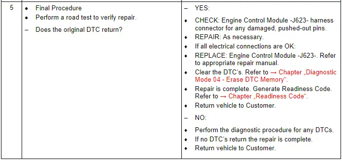
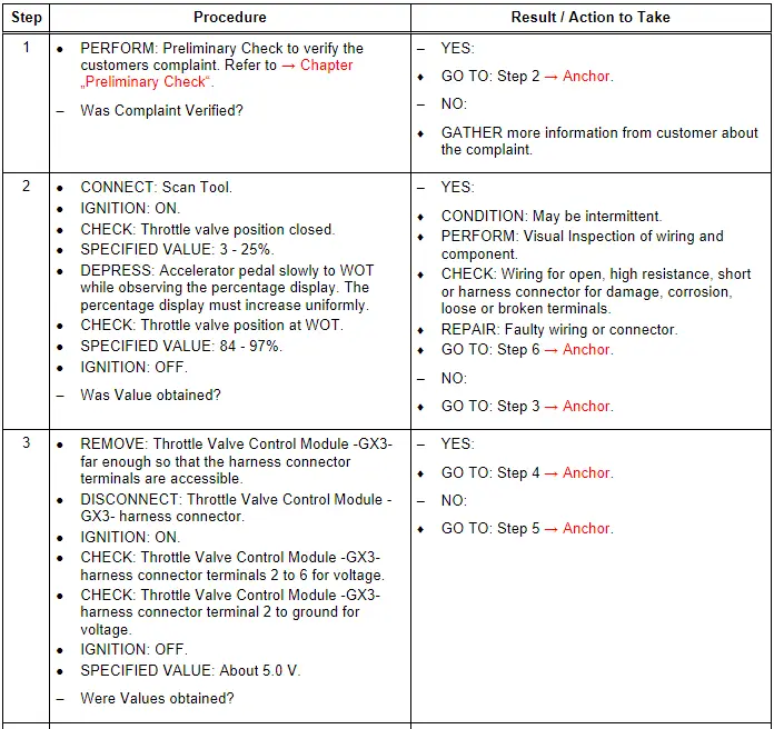
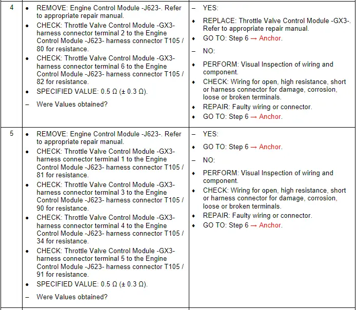
Throttle Valve Control Module - GX3-, Checking
General Description
Throttle valve operation occurs by an electric motor identified as the EPC Throttle Drive -G186- located within the Throttle Valve Control Module -GX3-. It is controlled by the Engine Control Module - J623- with primary inputs from the Accelerator Pedal Module -GX2- as well as other peripheral inputs from the EPC Throttle Drive Angle Sensor 1 -G187- and the EPC Throttle Drive Angle Sensor 2 -G188-.
Note the Throttle Valve Control Module - GX3- is also referred to as the Throttle Valve Control Module -J338-.
The Throttle Valve Control Module -GX3 / J338- contains the following components:
- Throttle Valve Control Module -J338-
- EPC Throttle Drive -G186-
- EPC Throttle Drive Angle Sensor 1 -G187-
- EPC Throttle Drive Angle Sensor 2 -G188-
The Throttle Valve Control Module -GX3 / J338- components cannot be serviced separately, and they must be serviced as a unit.
Special tools and workshop equipment required
- Multimeter.
- Wiring Diagram.
- Scan Tool.
Test requirements
- Fuses OK.
- Battery voltage OK.
- Switch OFF all electrical and electronic accessories.
- Vehicles with automatic transmission, ensure the selector lever position is in "P".
- Vehicles with manual transmission, ensure the shifter lever position is in "N" with the parking brake applied.
- Coolant temperature: ≥ 80º C.
- Observe all safety precautions: → Chapter "Safety Precautions".
- View clean working conditions: → Chapter "Clean Working Conditions".
- For Hybrid vehicles, refer to: → Chapter "High Voltage System General Warnings".
Test Procedure

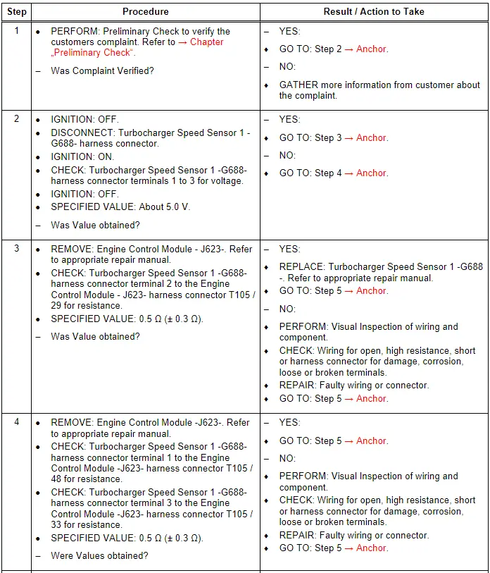
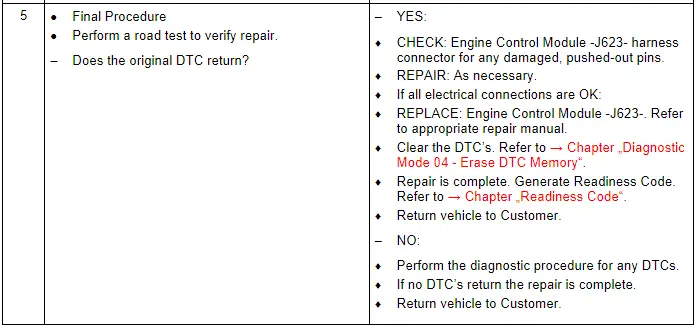
Turbocharger Speed Sensor 1 - G688-, Checking
General Description
The supercharger speed sensor detects the speed of the mechanically driven supercharger and transmits this information to the Engine Control Module -J623-.
Special tools and workshop equipment required
- Multimeter.
- Wiring Diagram.
- Scan Tool.
Test requirements
- Fuses OK.
- Battery voltage OK.
- Switch OFF all electrical and electronic accessories.
- Vehicles with automatic transmission, ensure the selector lever position is in "P".
- Vehicles with manual transmission, ensure the shifter lever position is in "N" with the parking brake applied.
- Coolant temperature: ≥ 80º C.
- Observe all safety precautions: → Chapter "Safety Precautions".
- View clean working conditions: → Chapter "Clean Working Conditions".
- For Hybrid vehicles, refer to: → Chapter "High Voltage System General Warnings".
Test Procedure
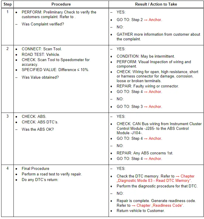
Vehicle Speed Signal, Checking
General Description
The Vehicle Speed Signal or VSS measures Transmission / Transaxle output or Wheel Speed from the ABS. The signal is broad casted over the CAN Bus. The Engine Control Module -J623- uses this information to modify engine functions such as ignition timing, A/F ratio, transmission shift points, and to initiate diagnostic routines.
Special tools and workshop equipment required
- Multimeter.
- Wiring Diagram.
- Scan Tool.
Test requirements
- Fuses OK.
- Battery voltage OK.
- Switch OFF all electrical and electronic accessories.
- Vehicles with automatic transmission, ensure the selector lever position is in "P".
- Vehicles with manual transmission, ensure the shifter lever position is in "N" with the parking brake applied.
- Coolant temperature: ≥ 80º C.
- Observe all safety precautions: → Chapter "Safety Precautions".
- View clean working conditions: → Chapter "Clean Working Conditions".
- For Hybrid vehicles, refer to: → Chapter "High Voltage System General Warnings".
Test Procedure