Audi Q7: Starter
Overview - Starter
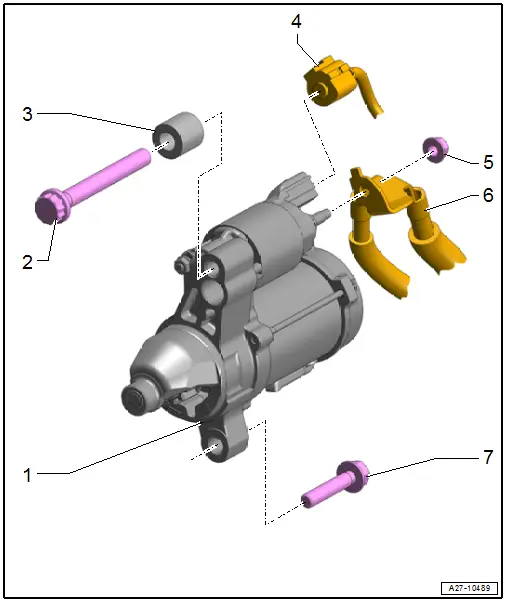
1 - Starter
- Removing and installing. Refer to → Chapter "Starter, Removing and Installing".
2 - Bolt
- Tightening specification. Refer to → Automatic Transmission; Rep. Gr.37; Transmission, Removing and Installing; Transmission Tightening Specifications.
3 - Spacer Sleeve
- Only on 4-cylinder engines
4 - Connector
5 - Nut
- 20 Nm
6 - B+ Terminal
7 - Bolt
- Tightening specification. Refer to → Automatic Transmission; Rep. Gr.37; Transmission, Removing and Installing; Transmission Tightening Specifications.
Starter, Removing and Installing
Starter, Removing and Installing, Vehicles with 3.0L TFSI Engine
Removing
- Turn off the ignition and disconnect the ground cable from the battery. Refer to → Chapter "Battery, Disconnecting and Connecting".
- Remove the right engine support. Refer to → 6-Cyl. TDI Common Rail 3,0l 4V Motor (EA 897 Gen I); Rep. Gr.13; Cylinder Block, Belt Pulley Side; Engine Support, Removing and Installing.
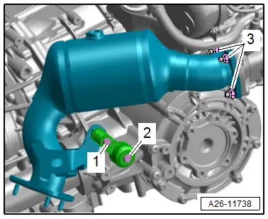
- Remove the bolts -1 and 2- and then remove the mounting.
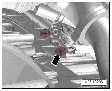
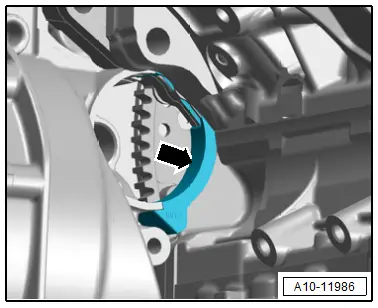
- Remove the bolt -arrow-.
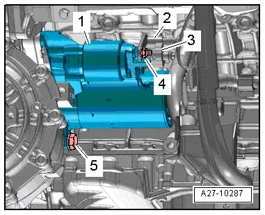
- Remove the bolt -5- and nut -4-.
- Remove the starter -1-, disconnect the connector -3- and free up the B+ wire -2-.
Installing
Install in the reverse order of removal while noting the following:
- Check the sealing piece -arrow- for the correct installation position.
- The area of the torque converter must be completely sealed.
TIP
If the starter assembly is difficult to move, use a silicone-free lubricating spray.
- Connect the battery. Required actions.
Tightening Specifications
- Refer to → Chapter "Overview - Starter"
- Refer to → Rep. Gr.26; Emissions Control System; Overview - Emissions Control System.
