Audi Q7: Tires, Changing
The valve insert must be replaced with every tire change.
Metal valve and wheel electronics can be reused.
- Let air out of tire by removing the valve insert.
 Note
Note
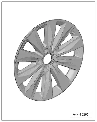
- Be careful not to scratch off the glued- on wheel trim on these rims.
- The surface of the wheel trim is very sensitive.
- The rim will have be replaced if the wheel trim is damaged.
- The wheel trim cannot be replaced.
- Tires, dismounting. Refer to → Fig. "Dismounting Tire".
Removing Run-Flat Tires. Refer to → Chapter "Removing Tires, Run-Flat Tires".
- Perform a visual inspection for loose or damaged parts. If there are loose threaded connections, replace entire valve unit.
 Note
Note
Damaged wheel electronics must be replaced.

Dismounting Tire
Roll or press tires off.
When using pressure paddles, first separate tires from side opposite of valve.
 Note
Note
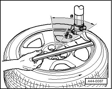
Do not use pressure paddles in hatched area -a-.
- Position mounting head near valve so that so that tire iron can be put on approximately 30º -b- next to tire valve.
- Then remove tire in valve area first.
Installing Run-Flat Tires. Refer to → Chapter "Tires, Mounting, Run-Flat Tires".
Mounting Tire
Do Not Use Pressure Paddles in Valve Area.
 Note
Note
- Be careful not to scratch off the glued- on wheel trim on these rims.
- The surface of the wheel trim is very sensitive.
- The rim will have be replaced if the wheel trim is damaged.
- The wheel trim cannot be replaced.
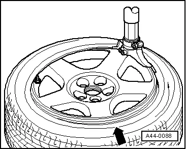
- Position wheel electronics approximately 180º opposite of mounting head.
- Press tire in bed approximately 90º in front of mounting head -arrow-.
- Install a new valve insert.
- Mount tire.
- Fill tires, reinstall plastic cap.
- Balance tires. Refer to → Chapter "Balancing".
- Install wheel.

Metal Valve Body, Removing and Installing
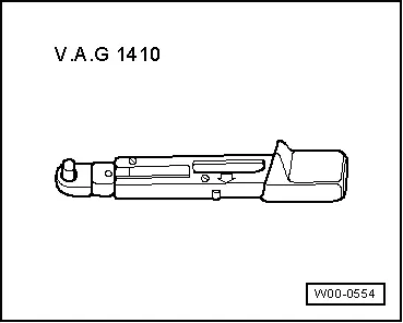
Special tools and workshop equipment required
- Torque Wrench 1410 -VAG1410- and Torque Wrench 1331 5-50Nm -VAG1331- 11 mm.
- Place metal valve with rubber seal through rim from inside.
- Attach chamfered washer and union nut from outside and tighten by hand.
- Tighten the union nut.
 Note
Note
- Be careful not to scratch off the glued- on wheel trim on these rims.
- The surface of the wheel trim is very sensitive.
- The rim will have be replaced if the wheel trim is damaged.
- The wheel trim cannot be replaced.
Union Nut Tightening Specification
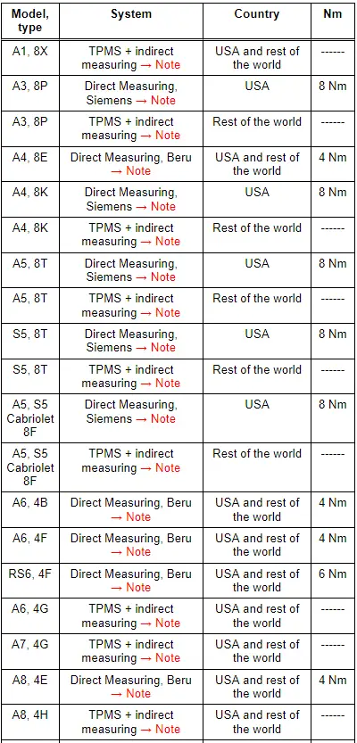
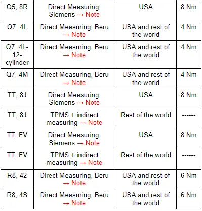
All other models: 4 Nm
1) TPMS direct measuring. The wheel electronics are installed inside the wheel on the metal valve; the tire pressure and temperature values are transmitted and evaluated periodically.
2) TPMS + indirect measuring. There are no wheel electronics installed inside the wheel. With the help of the ABS sensors, the TPMS compares the speed and rolling circumference of the individuals wheels. The loss of pressure is determined indirectly. If there is a change in the tire pressure, then the speed and the rolling circumference of wheel will also change.
3) TPMS indirect measuring. There are no wheel electronics installed inside the wheel. With the help of the ABS sensors, the TPMS compares the rolling circumference of the individual wheels. The loss of pressure is determined indirectly. If there is a change in the tire pressure, then the speed of the tire will also change.
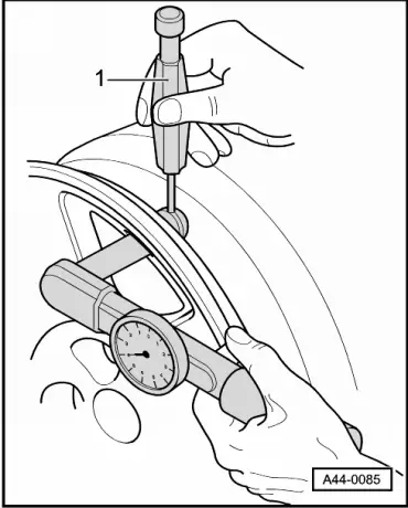
- Secure against turning with counterhold -1- (for example, a 2 mm drill bit).
 Note
Note
- Be careful not to scratch off the glued- on wheel trim on these rims.
- The surface of the wheel trim is very sensitive.
- The rim will have be replaced if the wheel trim is damaged.
- The wheel trim cannot be replaced.

Wheel Electronics System (Tire Pressure Monitoring System), Beru
Overview, Beru System
 WARNING
If tire sealant was used, then the wheel electronics on that particular wheel must be replaced.
 WARNING
Damaged wheel electronics must be replaced.
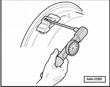
- Push the wheel electronics -1- into the bed.
- Install on the valve from the back with a microencapsulated screw.
 Note
Note
- Replace the microencapsulated screw.
- Tighten the microencapsulated screw to 4 Nm on all models.
Special tools and workshop equipment required
- Torque Wrench 1410 -VAG1410- and Torque Wrench 1410 Insert - Accessory Kit-VAG1410/1-
Tightening specification for all models: 4 Nm
Wheel Electronics System (Tire Pressure Monitoring System), Siemens
 WARNING
If tire sealant was used, then the wheel electronics on that particular wheel must be replaced.
- The Siemens wheel electronics does not have a microencapsulated screw.
- A union nut holds the wheel electronics in place inside the rim -item 7-.
- The metal valve body serves as an antenna.
- The connection between the metal valve body to the wheel electronics must not get damaged.
 WARNING
Counterhold the metal valve from the back by hand when pressing the wheel electronics into the bed on the rim. The connection between the metal valve to the wheel electronics must not get interrupted or damaged. Damaged wheel electronics must be replaced.
- Press the wheel electronics into the bed.
- Tighten the wheel electronics to the metal valve with the union nut. Refer to → Chapter "Metal Valve Body, Removing and Installing"

