Audi Q7: Trailer Hitch
Trailer Hitch Socket, Removing and Installing - Version 1
Removing
- Turn off the ignition and remove the key.
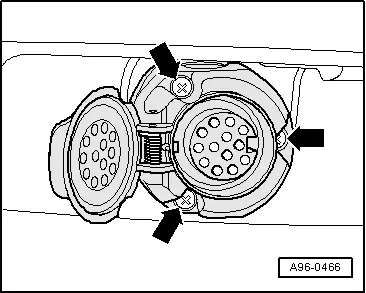
- Remove the bolts -arrows-.
- Detach the socket from the retaining plate.
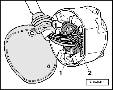
Socket with Rear Fog Lamp Shut-Off Contact Switch -F216-:
- Remove harness connector -2- for the Rear Fog Lamp Shut-Off Contact Switch -F216- and harness connector -1- from the Trailer Socket -U10-.
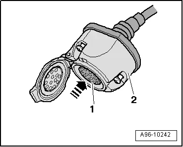
Socket without a Rear Fog Lamp Shut-Off Contact Switch -F216-:
- Press multiple connector -1- in direction of -arrow- out of socket -2-.
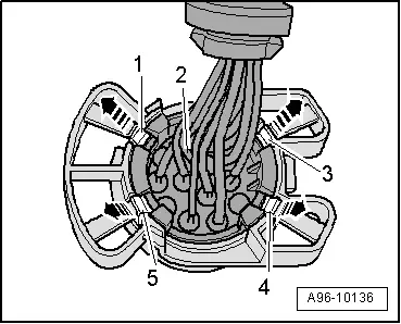
Version 1
- Release securing tabs in direction of -arrows- and then release retainer clips -1 and 3 through 5-.
- Remove the retainer from the connectors -2-.
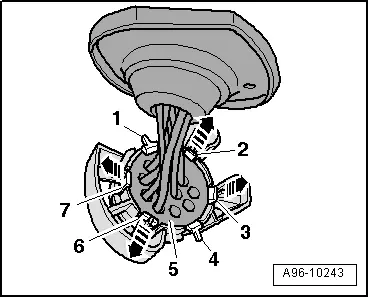
Version 2
- First release securing tabs in direction of -arrows- and then retaining clips -1, 2, 3, 4, 6, and 7-.
- Remove the retainer from the multi-pin connector -5-.
Installing
Install in reverse order of removal. Note the following:
 Note
Note
Make sure the O-rings -1 and 3- are not damaged.
- Slide the connectors -4- into the retainer -2- until they click into place.
Trailer Hitch Socket, Removing and Installing - Version 2
Removing
 Note
Note
During installation, install the cable ties at the same location.
- Turn off the ignition and remove the key.
- Unfold and engage the trailer hitch.
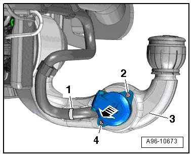
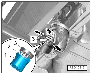
- Cut the cable tie -1- and remove the screws -2 and 4-.
- Press the socket out of trailer hitch -3- in direction of -arrow-.
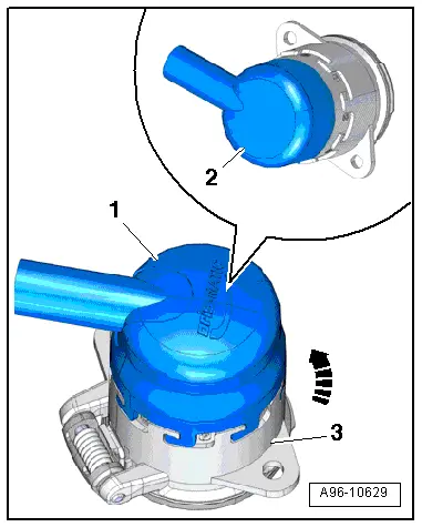
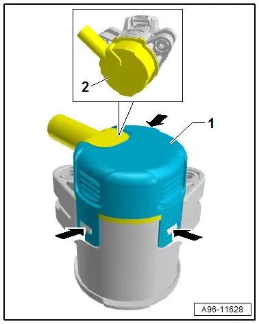
- Turn cap -1- counterclockwise -arrow- and remove it from socket -3-.
- Remove rubber cover -2-.
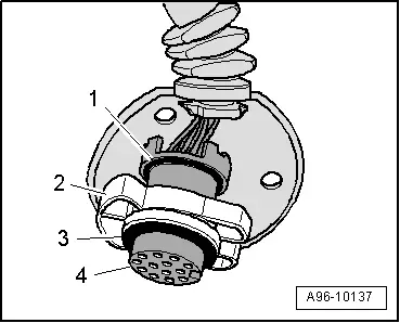
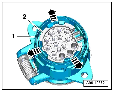
- Release the retaining clips -arrows- and press multiple connector -2- out of socket -1-.

- Release the retaining clips -arrows- and remove retainer -1- from multiple connector -3-.
 Note
Note
Carefully remove the retainer so that contacts -2- of the multiple connector are not disconnected from the wiring harness.

Installing
Install in reverse order of removal. Note the following:
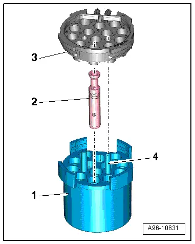
- The retainer -1- can be pushed onto multiple connector -3- in only one position.
- Guide pins -4- can be inserted into the retainer in only one position. Contacts -2- must be inserted in the retainer for this purpose.
- Insert the retainer into the multiple connector until it engages audibly.

Trailer Hitch Socket, Removing and Installing - Version 3
Removing
- Fold out the trailer hitch. Refer to the vehicle Owner's Manual.
- Switch off the ignition and remove the ignition key.
- Remove the bolts -arrows-.
- Remove the socket from the retaining plate.
- Remove the rubber cover from the socket.

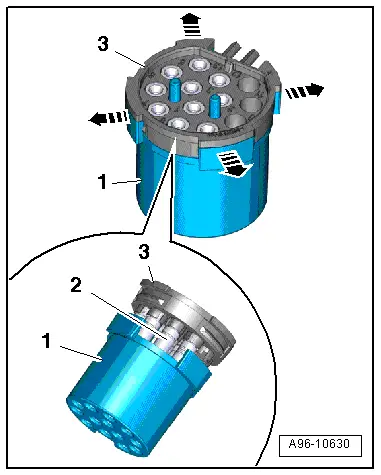
- Release the retaining clips in direction of -arrows- and press multiple connector -1- out of socket -2-.
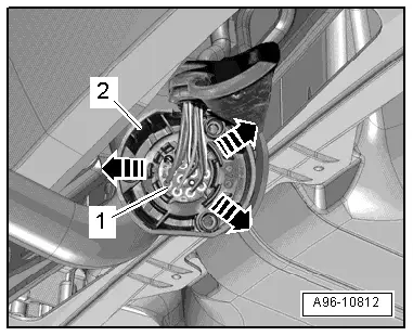
- Release the retaining clips in direction of -arrows- and remove retainer -2- from multiple connector -3-.
 Note
Note
Carefully remove the retainer so that contacts -2- of the multiple connector are not disconnected from the wiring harness.
Installing
Install in reverse order of removal. Note the following:
- The retainer -1- can be pushed onto multiple connector -3- in only one position.
- Guide pins -4- can be inserted into the retainer in only one position. Contacts -2- must be inserted in the retainer for this purpose.
- Insert the retainer into the multiple connector until it engages audibly.
Trailer Hitch Socket, Removing and Installing - Version 4
Removing
 Note
Note
During installation, install the cable ties at the same location.
- Turn off the ignition and all electrical equipment.
- Move out the trailer hitch.
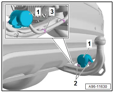
- Cut through the cable tie -3-.
- Remove the bolts -2-.
- Remove the socket from the trailer hitch -1-.
- Release the retainers -arrows-.
- At the same time remove the cap -1- from the socket.
- Remove rubber cover -2-.
- Release the clips -arrows- and press multiple connector -2- out of socket -1-.
- Release the clips -arrows- and remove retainer -1- from multiple connector -3-.
 Note
Note
Carefully remove the retainer so that contacts -2- of the multiple connector are not disconnected from the wiring harness.
Installing
Install in reverse order of removal. Note the following:
- The retainer -1- can be pushed onto multiple connector -3- in only one position.
- Guide pins -4- can be inserted into the retainer -1- in only one position. Contacts -2- must be inserted in the retainer for this purpose.
- Insert the retainer into the multiple connector until it engages audibly.


