Audi Q7: Windshield Projection Head Up Display Control Module, Removing and Installing
- If replacing the control module, select the "Replace control module" function for the corresponding control module on the Vehicle Diagnostic Tester
Removing
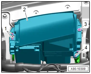
- Cover the control module -2- with a soft towel.
- Remove the windshield. Refer to → Body Exterior; Rep. Gr.64; Windshield; Windshield, Removing and Installing.
- Remove the windshield projection trim. Refer to → Body Interior; Rep. Gr.70; Instrument Panel; Overview - Instrument Panel.
 NOTICE
Risk of destroying the windshield projection head up display control module
- Only remove the designated bolts from the control module.
- Never remove the bolts for the housing upper section.
- Remove the bolts -1, 3 and 4-.
- Lift the control module slightly and disconnect the connector.
- Remove the control module.
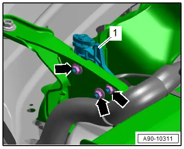
Removing the Exterior Bracket
- Remove the instrument panel. Refer to → Body Interior; Rep. Gr.70; Instrument Panel; Instrument Panel, Removing and Installing.
- Remove the nuts -arrows-.
- Remove the bracket -1-.
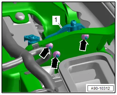
Removing the Inner Bracket
- Remove the instrument panel. Refer to → Body Interior; Rep. Gr.70; Instrument Panel; Instrument Panel, Removing and Installing.
- Remove the nuts -arrows-.
- Remove the bracket -1-.
Installing
Install in reverse order of removal. Note the following:
 NOTICE
Risk of destroying the windshield projection head up display control module
- A control module that has fallen down cannot be used again.
- When inserting the control module never apply pressure on the housing upper section.
- Check the function of the control module.
- A number must be appear on the windshield.
- Calibrate the windshield projection control module. Refer to → Chapter "Windshield Projection Head Up Display Control Module, Calibrating".
Tightening Specifications
- Refer to → Fig. "Windshield Projection Head Up Display Control Module - Tightening Specification and Sequence"
Windshield Projection Head Up Display Control Module, Calibrating
Special tools and workshop equipment required
- Vehicle Diagnostic Tester
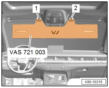
- Calibration Board for Head-Up Display VAS721003 -VAS721003-
Conditions
- The windshield projection control module must be calibrated during the following conditions:
- The Windshield Projection Head Up Display Control Module -J898- was replaced.
- The windshield was removed and installed.
- "No or incorrect basic setting/adaptation" is stored in the DTC memory.
Preliminary Work
- Move the vehicle onto a secure flat surface.
- Apply the parking brake - the vehicle must not move during the measurement.
- Fold down the left and right sun visors, disengage them and move them to the side.
- Engage the Calibration Board for Head-Up Display VAS721003 -VAS721003- on the center support -1 and 2- for the sun visor.
Calibrating
- The Vehicle Diagnostic Tester is connected.
- Select the Diagnostic mode and start.
- Select the Test plan tab.
- Press the Select individual tests button and select the following one after the other:
- Body
- Electrical Equipment
- 01 - OBD-capable systems
- 82 - Windshield Projection Head Up Display Control Module - J898
- 82 - Windshield projection control module, function
- 82 - Calibrating the head up display
- Start the selected program and follow the instructions in the Vehicle Diagnostic Tester display.
- After calibrating the windshield projection head up control module successfully, end "calibration", turn off the ignition and disconnect the diagnostic connector.

