Audi Q7: Display Control Head, Removing and Installing
General Information
 Note
Note
- Depending on vehicle equipment, there are different versions of the A/C system for the Audi Q7. Make sure to use the correct version and pay attention to the allocation of different components. Refer to → Chapter "A/C System Versions" and Parts Catalog.
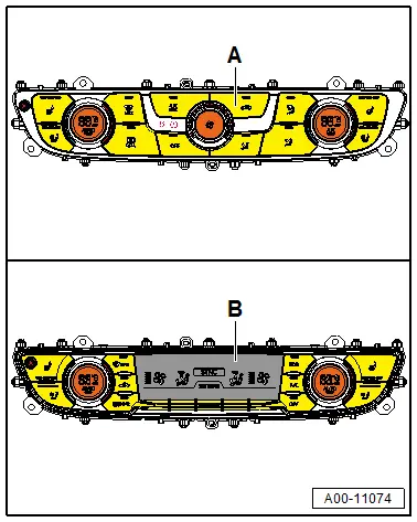
- There are different versions of the Front A/C Display Control Head -E87-. The Front A/C Display Control Head -E87- version -A- is installed for example in a "Low" or "Mid" A/C system. The version -B- is installed in a "Mix" or "High" A/C system. Refer to Vehicle Diagnostic Tester in the "Guided Fault Finding" function and refer to the Parts Catalog. Pay attention to the correct allocation and version when replacing.
Front A/C Display Control Head -E87-, Removing and Installing
- Check the coding and the adaptation of the Front A/C Display Control Head -E87- via the "replace control module" function of the Guided Fault Finding (if the -Front A/C Display Control HeadE87- is to be replaced). Refer to Vehicle Diagnostic Tester in the "Guided Fault Finding" function.
Removing
- Turn off the ignition.
 Caution
- To prevent damage to the Front A/C Display Control Head -E87- and the center console during removal, do not pull too tightly or press.
- Do not damage the surface of the instrument panel and the center console trim when removing (cover it for example).
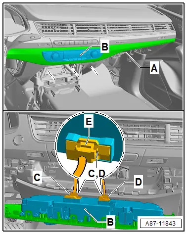
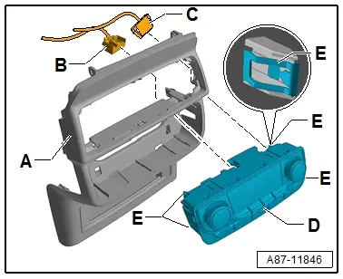
- Remove the right instrument panel trim -A- with the Front A/C Display Control Head -E87--B- from the instrument panel. Refer to → Body Interior; Rep. Gr.70; Instrument Panel; Overview - Instrument Panel.
- Mark the connector -C and D-.
 Caution
Risk of interchanging with other identical in construction connectors in the center console.
- Damage to control modules by connecting an incorrect connector
- Label connectors prior to removal from the control modules.
There is a risk of damaging the trim.
Carefully handle the trim and do not place it on the exposed side.
 Note
Note
The connector -D- is only present on a Front A/C Display Control Head -E87- for a "Mix" or "High" A/C system.
- Loosen the locking mechanism -E- of the connector -C- (and -D-).
- Remove the connector -C- (and -D-).
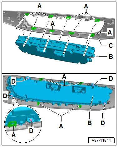
- Carefully release the bracket -A- and loosen the Front A/C Display Control Head -E87--B- from the trim -C-.
 Note
Note
Depending on the version (and if the bracket -A- does not hold properly) the Front A/C Display Control Head -E87--B- can also be secured with bolts -D- on the trim -C-.
Installing
Install in reverse order of removal. Note the following:
- When replacing a Front A/C Display Control Head -E87--B-, ensure the exact allocation. Refer to the Parts Catalog.
- To prevent damage to the trim -C-, carefully insert the Front A/C Display Control Head -E87--B- into the receiving shaft and then press in.
 Caution
There is a risk of damaging the trim.
Carefully handle the trim and the Front A/C Display Control Head -E87- and do not place on the exposed side.
- Check the Front A/C Display Control Head -E87--B- after inserting in the trim -C- for correct seating of the bracket -A-.
 Note
Note
If the bracket -A- is not routed correctly or doesn't hold the Front A/C Display Control Head -E87--B- must be secured with screws -D- (4.0 x 12 mm flat-head screws for example N 104 159) (Refer to the Parts Catalog.) in the trim -C- (tightening specification 1.2 Nm)
- After replacing / installing the Front A/C Display Control Head -E87-, always perform the following procedures. Refer to Vehicle Diagnostic Tester in the "Guided Fault Finding" function.
- Recode the Front A/C Display Control Head -E87- (or check the coding).
- Perform the basic setting of the Front A/C Display Control Head -E87-.
- Check the event memory of the Front A/C Display Control Head -E87- (correct any displayed malfunctions) and erase.
- Check the adaptation of the Front A/C Display Control Head -E87- and correct if necessary.
- Perform the output diagnostic test mode of the Front A/C Display Control Head -E87- (depending on the present complaint).
Rear A/C Display Control Head - E265-, Removing and Installing, "Mid" or "Mix" A/C System
 Note
Note
There are various versions of the Rear A/C Display Control Head -E265-, this version is for example installed on a "Mid" or "Mix" A/C system. Refer to Vehicle Diagnostic Tester in the "Guided Fault Finding" function. Refer to the Parts Catalog. Pay attention to the correct allocation and version when replacing.
Removing
- Turn off the ignition.
- Remove the rear center console trim -A-. Refer to → Body Interior; Rep. Gr.68; Center Console; Center Console Bracket, Removing and Installing.
- Loosen the locking mechanism of the connector -C- (and -D-).
- Remove the connector -C- (and -D-).
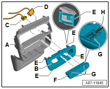
- Loosen the clamps -E- and trim -B-. Refer to → Body Interior; Rep. Gr.68; Center Console; Center Console Bracket, Removing and Installing.
- Loosen the clamp -G- (for example with a small screwdriver -H-) and remove the Rear A/C Display Control Head -E265--F-.
Installing
Install in reverse order of removal. Note the following:
- When replacing a Rear A/C Display Control Head -E265--A-, ensure the exact allocation. Refer to the Parts Catalog.
- Check the clamps -E and G- for correct seating on the trims -A and B-.
- To prevent damage to the center armrest trim, carefully insert the Rear A/C Display Control Head -E265--F- into the receiving shaft and then press in.
- After replacing / installing the Rear A/C Display Control Head -E265-, always perform the following procedures. Refer to Vehicle Diagnostic Tester in the "Guided Fault Finding" function.
- Recode the Front A/C Display Control Head -E87- (or check the coding).
- Perform the basic setting of the Front A/C Display Control Head -E87-.
- Check the event memory of the Front A/C Display Control Head -E87- (correct any displayed malfunctions) and erase.
- Check the adaptation of the Front A/C Display Control Head -E87- and correct if necessary.
- Perform the output diagnostic test mode of the Front A/C Display Control Head -E87- (depending on the present complaint).
Rear A/C Display Control Head -E265-, Removing and Installing, "High" A/C System
 Note
Note
There are various versions of the Rear A/C Display Control Head -E265-, this version is for example installed on a "High" A/C system. Refer to Vehicle Diagnostic Tester in the "Guided Fault Finding" function and refer to the Parts Catalog. Pay attention to the correct allocation and version when replacing.
Removing
- Turn off the ignition.
- Remove the rear center console trim -A-. Refer to → Body Interior; Rep. Gr.68; Center Console; Center Console Bracket, Removing and Installing.
- Loosen the locking mechanism of the connector -B- (and -C-).
- Remove the connector -B- (and -C-).
- Loosen the clamp -E- and remove the Rear A/C Display Control Head -E265--D-.
Installing
Install in reverse order of removal. Note the following:
- When replacing a Rear A/C Display Control Head -E265--D-, ensure the exact allocation. Refer to the Parts Catalog.
- Check the clamps -E- are seated correctly on the trim -A-.
- To prevent damage to the cover of the center armrest, carefully insert the Rear A/C Display Control Head -E265--D- into the receiving shaft of the trim -A- and then press in.
- After replacing / installing the Rear A/C Display Control Head -E265-, always perform the following procedures. Refer to Vehicle Diagnostic Tester in the "Guided Fault Finding" function.
- Recode the Rear A/C Display Control Head -E265- (or check the coding).
- Perform the basic setting of the Rear A/C Display Control Head -E265-.
- Retrieve the Rear A/C Display Control Head -E265- and the Rear A/C Display Control Head -E265- DTC memory (correct any displayed malfunctions) and erase.
- Check the adaptation of the Rear A/C Display Control Head -E265- and correct if necessary.
- Perform the output diagnostic test mode of the Rear A/C Display Control Head -E265- (depending on the present complaint).

