Audi Q7: A/C Technology Basic Principles
Physical Principles
The four known states of water also apply to air conditioning system refrigerants.
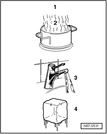
1 - Gaseous (invisible)
2 - Vapor
3 - Liquid
4 - Solid
When water is heated in a container (heat absorption), water vapor can be seen to rise. If the vapor is further heated through heat absorption, the visible vapor turns into invisible gas. The process is reversible. If heat is extracted from water in gaseous form -A-, it changes first to vapor -B-, then to water and finally to ice.
A - Heat absorption
B - Heat emission
Heat Transfer
Every substance consists of a mass of moving molecules. The fast moving molecules of a warmer substance give off some of their energy to the cooler and thus slower molecules. As a result, the molecular motion of the warmer substance slows down and that of the colder substance is accelerated. This process continues until the molecules of both substances are moving at the same speed. They are then at the same temperature and no further heat exchange takes place.
Pressure and Boiling Point
The boiling point given in tables for a liquid is always referenced to an atmospheric pressure of 1 bar (14.5 psi). If the pressure acting on a fluid changes, its boiling point also changes.
 Note
Note
Pressure is measured in different units: 1 MPa (145 psi) corresponds to 10 bar (145 psi) positive pressure. 1 bar (14.5 psi) absolute pressure corresponds to 0 bar/psi positive pressure and thus to the ambient pressure (atmospheric pressure).
Water boils at a lower temperature the lower the pressure.
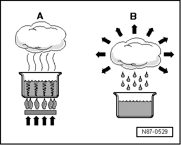
The vapor pressure curves for water and refrigerant R134a show that, at constant pressure, reducing the temperature changes vapor to liquid (in the condenser) or that reducing the pressure causes the refrigerant to change from liquid to vapor (inside the evaporator).
Vapor pressure curve of water
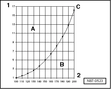
A - Liquid
B - Gas
C - Vapor pressure curve of water
1 - Pressure acting on liquid in bar (psi)
2 - Temperature in ºC (ºF)
Vapor pressure curve of refrigerant R134a
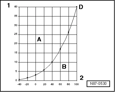
A - Liquid
B - Gas
D - Vapor pressure curve of refrigerant R134a
1 - Pressure acting on liquid in bar (psi)
2 - Temperature in ºC (ºF)
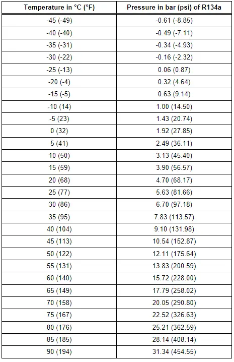
Refrigerant R134a Vapor Pressure Table
The vapor pressure table for every refrigerant is published in literature for the refrigeration system engineers. This table makes it possible to determine the vapor pressure acting on the column of liquid in a container if the temperature of the container is known.
Because each refrigerant has its own characteristic vapor pressure table, refrigerant can be identified by measuring the pressure and temperature.
 Note
Note
- At absolute pressure, "0 bar/psi" corresponds to absolute vacuum. Normal ambient pressure (positive pressure) equals approximately "1 bar (1.5 psi)" absolute pressure. "0 bar/psi" pressure corresponds to an absolute pressure of 1 bar (14.5 psi) on most pressure gauges (indicated by "-1 bar (-14.5 psi)" below "0 bar/psi").
- Pressure is measured in different units: 1 MPa (145 psi) corresponds to 10 bar (145 psi) positive pressure. 1 bar (14.5 psi) absolute pressure corresponds to 0 bar/psi positive pressure and thus to the ambient pressure (atmospheric pressure).