Audi Q7: Axle Alignment Specified Values
Conditions
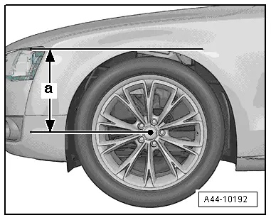
- The settings specified apply to the curb weight position or the standard vehicle height of the vehicle. To determine the curb weight position or the standard vehicle height the dimension -a- between the center of the wheel and the lower edge of the fender/wheel housing. When the curb weight position or the standard vehicle height is not OK then a correct axle alignment cannot be performed.
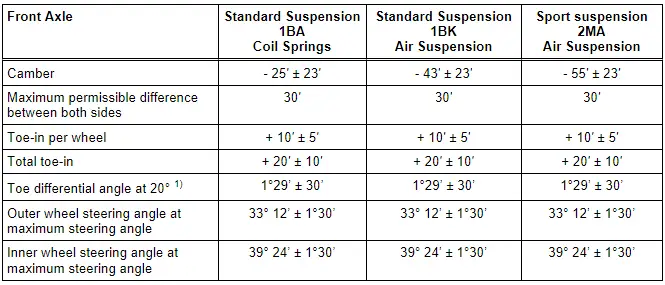
1) Angle of outer wheel is less by this amount. It can also be indicated negatively in alignment computer, depending on manufacturer.
Additional Vehicle Data
This additional vehicle data only serves for a faster diagnosis in the case of accidents.
Rear Axle Camber, Adjusting
Procedure
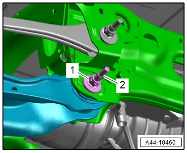
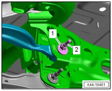
- Remove the nut -1- from the subframe/rear lower transverse link threaded connection and install the new nut all the way.
- Adjust the camber by rotating the adjusting bolt -2-.
 Note
Note
To turn the adjusting bolt, turn the hex head at the "top of the bolt".
- Axle alignment specified values. Refer to → Chapter "Axle Alignment Specified Values".
 Note
Note
- The maximum adjustment range is 135º to left or right of center position.
- Do not rotate the adjusting bolt -2- further once the end position has been reached or the components will be damaged.
- For clarity the rear wheel is not shown.
- Tighten the nut -1-.
- Then check the camber value again. Refer to → Chapter "Axle Alignment Specified Values".
Tightening Specifications
- Refer to → Chapter "Overview - Transverse Link"
Rear Axle Toe, Adjusting
Special tools and workshop equipment required
- Pawl with fine gear, commercially available
Procedure
Vehicles without Rear Axle Steering:
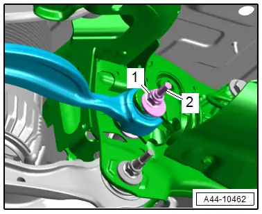
- Remove the nut -1- from the threaded connection tie rod/subframe, and install the new nut until stop.
- Adjust the toe by rotating eccentric bolt -2-.
 Note
Note
To turn the eccentric bolt, turn the hex head at the "top of the bolt".
Vehicles with Rear Axle Steering:
- Remove the nut -1- from the threaded connection tie rod/rear axle steering, and install the new nut until stop.
- Adjust the toe by rotating eccentric bolt -2-.
Continuation for All Vehicles:
- Axle alignment specified values. Refer to → Chapter "Axle Alignment Specified Values".
 Note
Note
- The maximum adjustment range is 90º to left or right of center position.
- The geometric drive axle is automatically changed when individual toe settings are changed.
- Tighten the nut -1- with the Track Rod Tool Insert -T40183-.
- Then check the toe value again. Refer to → Chapter "Axle Alignment Specified Values".
Tightening Specifications
- Refer to → Chapter "Overview - Transverse Link"
Front Axle Camber, Centering
 Note
Note
- Camber cannot be adjusted.
- Camber can be centered evenly within specified tolerance range by shifting subframe.
Procedure
- Remove the noise insulations. Refer to → Body Exterior; Rep. Gr.66; Noise Insulation; Noise Insulation, Removing and Installing.
- Remove the front lower longitudinal member. Refer to → Body Exterior; Rep. Gr.50; Lock Carrier; Lock Carrier, Removing and Installing.
 Caution
There is a risk of damaging the threads on the subframe threaded connection to the body.
- The subframe bolts on the body must not be loosened or tightened with an impact wrench.
- Always install all bolts by hand for the first few turns.
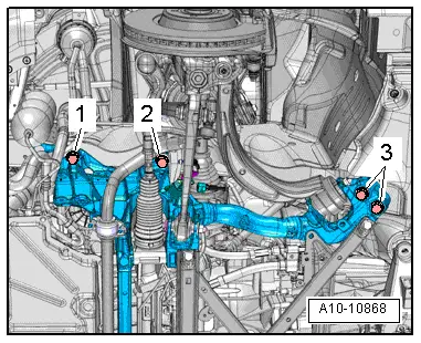
- Remove the left and right bolts -1, 2 and 3- for the subframe one after the other and replace.
- Install the new bolts all the way by hand.
 Note
Note
If the subframe is moved, the front of the vehicle must be lifted at the jack points using an axle lift.
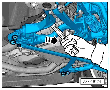
- Move the subframe with a plastic-coated pry bar into the corresponding position in direction of -arrow-.
- To do so place the pry bar in the center of the subframe near the control arm between the subframe and the body longitudinal member.
 Note
Note
If no plastic-coated pry bar is available, wrap a conventional pry bar with adhesive tape.
- The vehicle must be bounced several times at the front axle before checking the camber values.
- Axle alignment specified values. Refer to → Chapter "Axle Alignment Specified Values".
 WARNING
Risk of accident!
Replace the bolts for the subframe one after the other.
- Tighten the left and right bolts for the subframe diagonally in steps.
 Caution
There is a risk of adjustment errors.
Every time camber is corrected, axle alignment values should be checked.
Tightening Specifications
- Refer to → Chapter "Overview - Subframe"
- Refer to → Body Exterior; Rep. Gr.66; Noise Insulation; Overview - Noise Insulation.
- Lower longitudinal member. Refer to → Body Exterior; Rep. Gr.50; Lock Carrier; Overview - Lock Carrier.
Front Axle Toe, Adjusting
Procedure
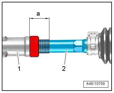
- Measure the dimension -a- between the tie rod head -1- and the left and right tie rod -2- and make a note of the value. Dimension -a- should be the same before and after adjusting on the left and right.
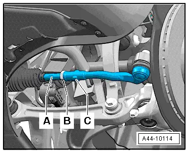
- Loosen the lock nut -B- to do so counterhold on the tie rod end -C-.
- Adjust toe on left and right-hand wheels at hex -A-.
 Caution
There is a risk of premature wear if the boot is twisted.
Be sure that boot is not twisted after turning tie rods.
- Tighten the lock nut -B-, -item 5- and check toe-in value again.
 Note
Note
- After tightening lock nut -B- it is possible that the value deviates slightly.
- If the measured toe nevertheless lies within the tolerance, the adjustment is correct.
Steering Angle Sensor -G85- Basic Setting
Special tools and workshop equipment required
- Vehicle Diagnostic Tester
- Steering Wheel Scales -VAS6458-
Procedure
Select this basic setting for the following activities:
- The Steering Column Electronics Control Module -J527- was replaced.
- The Active Steering Control Module -J792- was replaced,
- The steering column was replaced.
- Connect the Vehicle Diagnostic Tester.
- Switch the ignition on.
- Select and start the Diagnostic operating mode.
- Select the Test plan tab.
- Select the button Individual tests and select the following tree structures one after the other:
- Body
- Electrical system
- 01 - OBD-capable systems
- 16 - Steering column electronics control module J527
- 16 - Steering column electronics control module function
- 16 - Steering Angle Sensor G85
- Start the selected program and follow the instructions in the display of the Vehicle Diagnostic Tester.

