Audi Q7: Driver Assistance Systems Front Camera
Driver Assistance Systems Front Camera, Calibrating
Special tools and workshop equipment required
- Vehicle Diagnostic Tester
- Wheel Alignment Computer
- Setting Device Basic Set -VAS6430/1-
- Adapter VAS6430/9 -VAS6430/9-, only for surface mounted hoist with a dimension greater than 300 mm.
Procedure
 Note
Note
- For surface mounted hoist with a dimension greater than 300 mm the Setting Device - Basic Set - VAS6430/1A- with the Adapter VAS 6430/9 -VAS6430/9- must be set higher.
- Check if the Setting Device Basic Set -VAS6430/1- is in the center position and is locked.
- Check if the Driver Assistance Systems Front Camera -R242- is seated correctly in the bracket.
- Check of the visible area of the Driver Assistance Systems Front Camera -R242- is free.
- Check the DTC memory and correct any malfunctions before beginning the calibration.
- Versions with air suspension: drive the vehicle at standard vehicle height
There are two choices for calibrating:
The "quick access"
This procedure should be selected for the following activities if only the calibration will be performed.
- "No or incorrect basic setting/adaptation" is stored actively in the DTC memory.
- the Driver Assistance Systems Front Camera -R242- was removed and installed or replaced,
- The windshield is replaced or removed,
- The standard vehicle height on vehicles with air suspension was reprogrammed.
The "complete alignment"
This procedure should be selected for the following activities if a calibration and a wheel alignment will be performed.
- The rear axle toe was adjusted.
- the vehicle suspension was changed, for example, changing from standard to sport suspension.
 Note
Note
Both procedures are programmed into the axle alignment computer. The respective procedure is performed automatically. It is only necessary to select the appropriate program for the procedure that will be performed.
Note the preparation work for calibrating driver assistance systems. Refer to → Chapter "Preparation Work for Calibrating and Adjusting Driver Assist Systems".
Calibrating without a Previous Axle Alignment
- Switch off the ignition when the vehicle has come to a stop. Only this way it can be ensured that the is in the straight-ahead position.
- Select the front camera calibration procedure in the alignment computer.
- Install the quick clamps on all four wheels.
- Mount the measurement sensor to the rear wheels.
- Perform a wheel run-out compensation and the rear wheels.
Calibrating with a Previous Axle Alignment
- Switch off the ignition when the vehicle has come to a stop. Only this way it can be ensured that the is in the straight-ahead position.
- Connect the battery charger. Refer to → Electrical Equipment; Rep. Gr.27; Battery; Battery, Charging.
- Position the front wheels so they are straight.
- Connect the Vehicle Diagnostic Tester to the vehicle and guide the diagnostic cable through the open window.
- Turn off all vehicle exterior lamps.
- Close all vehicle door.
Calibrating/Adjusting Procedure with or without a Previous Axle Alignment
- Select the front camera calibration procedure in the alignment computer.
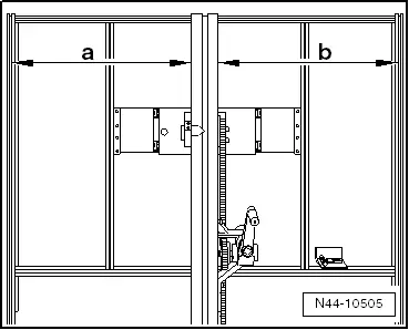
- Make sure the calibration board is positioned in the center and is locked in place.
- Dimension -a- = dimension -b-.
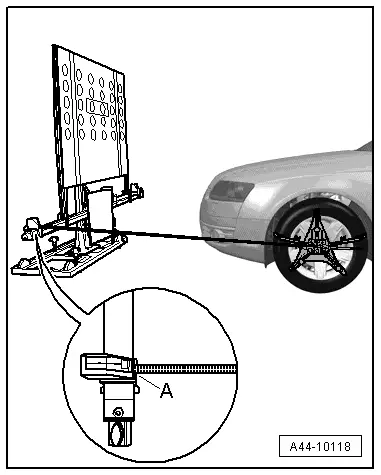
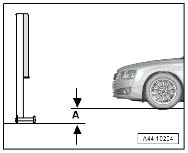
- Position the Setting Device Basic Set -VAS6430/1- at a distance of -A- 150 cm +- 2.5 cm from the center of the wheel hub on the front wheels to the beam on the Setting Device Basic Set -VAS6430/1- as shown in the illustration.
 Note
Note
The Setting Device Basic Set -VAS6430/1A- must not be moved on the calibration beam.
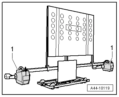
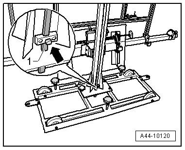
- Mount the front wheel measuring sensors -1- to the Setting Device Basic Set -VAS6430/1A-.
 Note
Note
The alignment stand must be in the lowest level position for the next step.
- Enter the height value -A- between the Setting Device Basic Set -VAS6430/1A- contact patch and the wheel contact surface as shown in the illustration and enter it in the alignment computer.
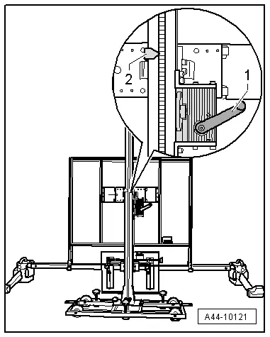
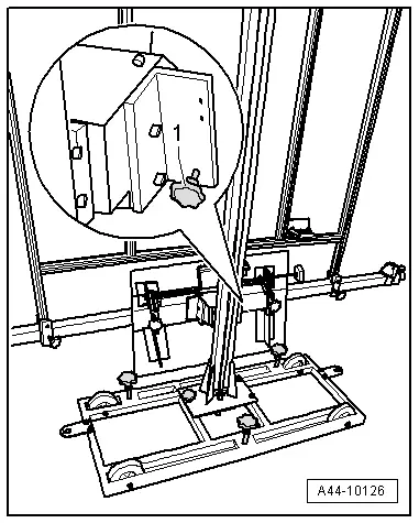
- Loosen the bolt -arrow- and place the measuring bar -1- on the floor.
- Adjust the calibration panel to the specified height -2- according to the alignment computer using the crank -1-.
If the specified height was reached -2-, then the measuring bar must be pushed slightly upward and secured with the clamping screw.
 Note
Note
If in later procedure the height of the calibration board must be corrected, make sure the measuring bar is touching the ground when this is being done.
- Level the bubble level -A- using the adjusting screw -1-.
The bubble adjustment -A- serves to compare the ground conditions.
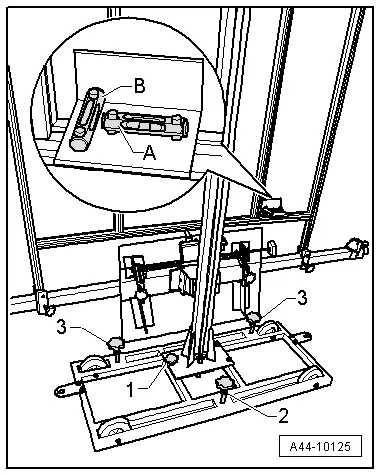
- Move the Setting Device Basic Set -VAS6430/1A- sideways in direction of -arrow B- until the display on the alignment computer is within the tolerance range.
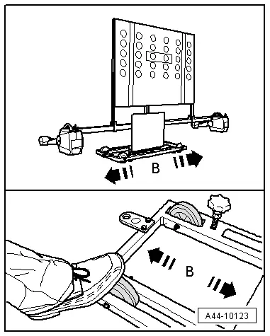
- Secure the Setting Device Basic Set -VAS6430/1- by tightening the bolts -2- and -3- slightly. (This prevents the Setting Device Basic Set -VAS6430- from rolling away).
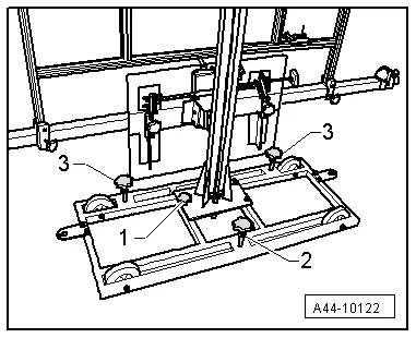
- Turn the precision adjustment screw -1- until the display on the wheel alignment computer is located within the tolerance range.
- Level the bubble level -A- using the adjusting screw -1-.

- Level the bubble level -B- using the adjusting screw -2-.
 Note
Note
Because after adjusting the bubble levels small height changes can result, the height of the calibration board must be checked again.
Perform any Subsequent Work Using the Vehicle Diagnostic Tester.
- Connect the Vehicle Diagnostic Tester.
- Switch the ignition on.
- Select and start the Diagnostic operating mode.
- Select the Test plan tab.
- Select the button Individual tests and select the following tree structures one after the other:
- Body
- 01 - OBD-capable systems
- A5 - Driver Assistance Systems Front Camera -R242
- A5 - Driver Assistance Systems Front Camera Functions
- A5 - Control module calibrating
- Start the selected program and follow the instructions in the display of the Vehicle Diagnostic Tester.
 Note
Note
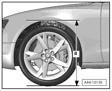
Next, determine the height of the body.

- Determine the body height -a- at all four wheels in the center of the wheel between the wheel contact surface and the lower edge of the fender.
Additional work, when the Driver Assistance Systems Front Camera -R242- is replaced:
- Adjust the headlamps. Refer to → Electrical Equipment; Rep. Gr.94; Headlamps; Headlamp, Adjusting.