Audi Q7: Defroster Door Motor -V107-, Removing and Installing
 Note
Note
- Currently in this vehicle, all actuators are identical in construction. During the basic setting, the actuators are assigned and adapted corresponding to the switching sequence of the wiring. If this sequence does not conform with the specification, the actuators will adapt incorrectly and the door control will be wrong. Refer to → Chapter "Main Wiring Diagram for A/C System Actuators".
- Therefore, perform the basic setting for the A/C system after installation of the adjustment motor. Refer to Vehicle Diagnostic Tester in the "Guided Fault Finding" function.
- Using the "output diagnostic test mode" and "basic setting" functions, the activation of A/C system electrical components can be tested if necessary (for example, allocation test). Refer to Vehicle Diagnostic Tester in the "Guided Fault Finding" function.
- After installing a new actuator, check the activation via the Front A/C Display Control Head -E87- and the actuator function. Refer to Vehicle Diagnostic Tester in the "Guided Fault Finding" function.
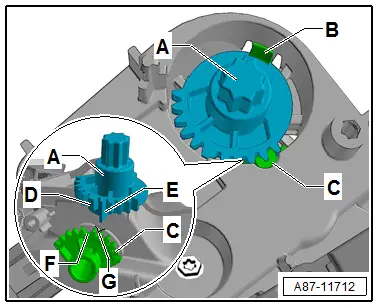
- The defroster door is not operated directly by the motor but rather by the Defroster Door Motor -V107- gears. The gears -A and C- are designed with a wide tooth -D- and a long tooth -E- or with a wide tooth interval -F- and a long tooth interval -G- so that it may only be joined in one position.
- So that the gear -A- does not fall out of the mount when the Defroster Door Motor -V107- is removed, it is held in position with a retaining tab -B-.
- If the gear -A- is pulled out of the bracket when removing the Defroster Door Motor -V107-, it can only be installed again correctly when the instrument panel is removed due to the difficult accessibility. Refer to → Chapter "Bracket for Left Adjustment Motors, Removing and Installing (on a LowMid A/C System)" and → Chapter "Bracket for Left Adjustment Motors, Removing and Installing (on a Mix or High A/C System)".
Removing
- Move the driver seat as far back as possible.
- Turn off the ignition.
- Remove the driver side instrument panel cover. Refer to → Body Interior; Rep. Gr.68; Storage Compartments and Covers; Driver Side Instrument Panel Cover, Removing and Installing.
- Remove the left footwell vent (driver side). Refer to → Chapter "Driver Side Footwell Vent, Removing and Installing".
- Loosen the left air duct above the central tube and push as far as possible to the outer side. Remove the air duct to the left instrument panel vent to do this. Refer to → Chapter "Overview - Air Routing and Air Distribution in Passenger Compartment, Front".

 Caution
A/C system malfunctions in the case of interchanged control motors and/or connectors. Refer to → Chapter "Main Wiring Diagram for A/C System Actuators".
- The adjustment motors and connectors are identical. If they are installed or connected incorrectly, the corresponding doors cannot be properly adapted and/or activated.
- Clearly label the actuators and connectors prior to removal to prevent incorrect installation.
 Note
Note
- Depending on vehicle equipment, there are different versions of the A/C system for the Audi Q7. Make sure to use the correct version and pay attention to the allocation of different components. Refer to → Chapter "A/C System Versions" and Parts Catalog.
- On right-hand drive vehicles, the Defroster Door Motor -V107--C- is not on the left side, but rather on the right side of the heater and A/C unit. The Right Center Vent Motor -V111- must be removed on these vehicles (instead of the Left Side Vent Motor -V299- and Left Center Vent Motor -V110-. Refer to → Chapter "Right Center Vent Motor -V111-, Removing and Installing".
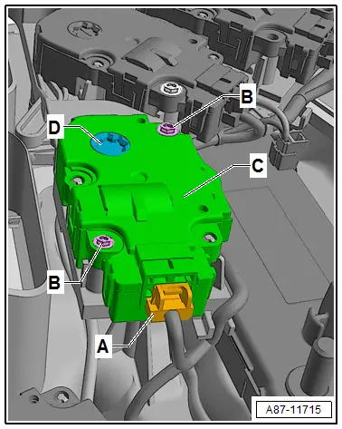
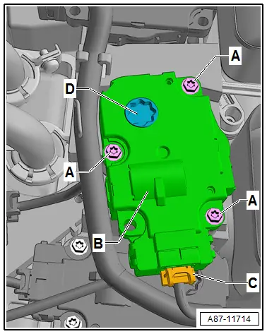
- Label the connector -A- and the actuator -C- (to avoid a mix up in case several connectors are disconnected at the same time).
- Disconnect the connector -A-.
- Remove the bolts -B-.
 Caution
The gear, through which the defroster door is operated, may also be pulled out when removing the actuator. The instrument panel must then be removed to install the gear.
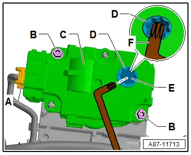
- When removing the actuator -C-, hold the shaft for gear -E- in place using, for example an angled screwdriver -F-.
- Carefully remove the actuator -C- from the bracket.
- Remove the actuator -C- from the shaft for gear -D-.

Installing
Install in reverse order of removal. Note the following:
- Check the gear -A- for correct installation.
- Check the defroster door actuation for function and ease of movement by turning the gear -A-.
 Caution
If the mount -B- for the actuator -C- is turned by hand, then the electronics in the actuator can be damaged.
 Note
Note
The actuator mount does not have a stop. It turns constantly if the actuator is activated. Therefore, this should not be activated with the adjustment motor removed.
- Check the shaft -A- and the mount -B- for the actuator -C-. They must be properly aligned so that they can be joined.
- Attach the actuator mount -B- to the door shaft -A-.
- Check the connection between the mount -D- for the actuator -C- and the shaft -E-; there must not be any play.
- Connect the connector -A-.
- Tighten the bolts -B-.
- Route the wiring harness to the connector -A- so that it cannot come in contact with any moving parts.
- Perform the basic setting and the output diagnostic test mode of the A/C system. Refer to Vehicle Diagnostic Tester in the "Guided Fault Finding" function.
 Note
Note
- Ignore item -F-.
- In this vehicle, the actuators are equipped with electronics. During the basic setting, a new control motor learns its position on the heater and A/C unit and can then be activated by the Front A/C Display Control Head -E87- (currently all actuators are identical). Refer to Vehicle Diagnostic Tester in the "Guided Fault Finding" function.
- During the basic setting, the actuators are assigned and adapted corresponding to the switching sequence of the wiring. If this sequence does not conform with the specification, the actuators will adapt incorrectly and the door control will be wrong. Refer to → Chapter "Main Wiring Diagram for A/C System Actuators".
- Check the DTC memory on the Front A/C Display Control Head -E87- and erase any displayed malfunctions. Refer to Vehicle Diagnostic Tester in the "Guided Fault Finding" function.
Left Footwell Door Motor -V108-, Removing and Installing
 Note
Note
- Depending on vehicle equipment, there are different versions of the A/C system for the Audi Q7. Make sure to use the correct version and pay attention to the allocation of different components. Refer to → Chapter "A/C System Versions" and Parts Catalog.
- The Left Footwell Door Motor -V108- is only installed on vehicles with a "Mix" or "High" A/C system. On vehicles with a "Low" or "Mid" A/C system, the left footwell door is actuated using the lever and a curved washer from the Left Side Vent Motor -V299-.
- Currently in this vehicle, all actuators are identical in construction. During the basic setting, the actuators are assigned and adapted corresponding to the switching sequence of the wiring. If this sequence does not conform with the specification, the actuators will adapt incorrectly and the door control will be wrong. Refer to → Chapter "Main Wiring Diagram for A/C System Actuators".
- Therefore, perform the basic setting for the A/C system after installation of the adjustment motor. Refer to Vehicle Diagnostic Tester in the "Guided Fault Finding" function.
- Using the "output diagnostic test mode" and "basic setting" functions, the activation of A/C system electrical components can be tested if necessary (for example, allocation test). Refer to Vehicle Diagnostic Tester in the "Guided Fault Finding" function.
- After installing a new actuator, check the activation via the Front A/C Display Control Head -E87- and the actuator function. Refer to Vehicle Diagnostic Tester in the "Guided Fault Finding" function.
- Refer to → Chapter "Bracket for Left Adjustment Motors, Removing and Installing (on a LowMid A/C System)"
Removing
- Move the driver seat as far back as possible.
- Turn off the ignition.
- Remove the driver side instrument panel cover. Refer to → Body Interior; Rep. Gr.68; Storage Compartments and Covers; Driver Side Instrument Panel Cover, Removing and Installing.
- Remove the left footwell vent (driver side). Refer to → Chapter "Driver Side Footwell Vent, Removing and Installing".
 Caution
A/C system malfunctions in the case of interchanged control motors and/or connectors. Refer to → Chapter "Main Wiring Diagram for A/C System Actuators".
- The adjustment motors and connectors are identical. If they are installed or connected incorrectly, the corresponding doors cannot be properly adapted and/or activated.
- Clearly label the actuators and connectors prior to removal to prevent incorrect installation.
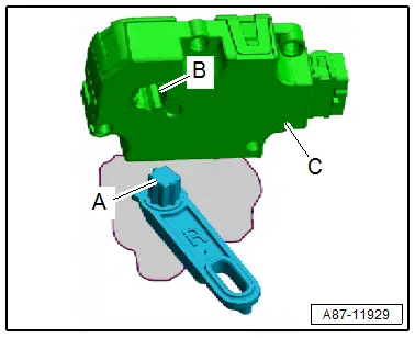
- Label the connector -C- (to prevent a mix up if several connectors are disconnected at the same time).
- Remove the bolts -A-.
- Remove the actuator -B- from the door shaft -D-.
- Disconnect the connector -C-.
Installing
Install in reverse order of removal. Note the following:
 Caution
If the mount -B- for the actuator -C- is turned by hand, then the electronics in the actuator can be damaged.
 Note
Note
The actuator mount does not have a stop. It turns constantly if the actuator is activated. Therefore, this should not be activated with the adjustment motor removed.
- Check the shaft -A- and the mount -B- for the actuator -C-. They must be properly aligned so that they can be joined.
- Attach the actuator mount -B- to the door shaft -A-.
 Note
Note
Check the connection between the actuator mount and the shaft; there must not be any play.

- Connect the connector -C- .
- Tighten the bolts -A-.
- Route the wiring harness to the connector -C- so that it cannot come in contact with any moving parts.
- Perform the basic setting and the output diagnostic test mode of the A/C system. Refer to Vehicle Diagnostic Tester in the "Guided Fault Finding" function.
 Note
Note
- In this vehicle, the actuators are equipped with electronics. During the basic setting, a new control motor learns its position on the heater and A/C unit and can then be activated by the Front A/C Display Control Head -E87- (currently all actuators are identical). Refer to Vehicle Diagnostic Tester in the "Guided Fault Finding" function.
- During the basic setting, the actuators are assigned and adapted corresponding to the switching sequence of the wiring. If this sequence does not conform with the specification, the actuators will adapt incorrectly and the door control will be wrong. Refer to → Chapter "Main Wiring Diagram for A/C System Actuators".
- Check the DTC memory on the Front A/C Display Control Head -E87- and erase any displayed malfunctions. Refer to Vehicle Diagnostic Tester in the "Guided Fault Finding" function.

Right Footwell Door Motor -V109-, Removing and Installing
 Note
Note
- Depending on vehicle equipment, there are different versions of the A/C system for the Audi Q7. Make sure to use the correct version and pay attention to the allocation of different components. Refer to → Chapter "A/C System Versions" and Parts Catalog.
- The Right Footwell Door Motor -V109- is only installed on vehicles with a "Mix" or "High" A/C system. On vehicles with a "Low" or "Mid" A/C system, the right footwell door is actuated using the lever and a curved washer from the Right Side Vent Motor -V300-.
- Currently in this vehicle, all actuators are identical in construction. During the basic setting, the actuators are assigned and adapted corresponding to the switching sequence of the wiring. If this sequence does not conform with the specification, the actuators will adapt incorrectly and the door control will be wrong. Refer to → Chapter "Main Wiring Diagram for A/C System Actuators".
- Therefore, perform the basic setting for the A/C system after installation of the adjustment motor. Refer to Vehicle Diagnostic Tester in the "Guided Fault Finding" function.
- Using the "output diagnostic test mode" and "basic setting" functions, the activation of A/C system electrical components can be tested if necessary (for example, allocation test). Refer to Vehicle Diagnostic Tester in the "Guided Fault Finding" function.
- After installing a new actuator, check the activation via the Front A/C Display Control Head -E87- and the actuator function. Refer to Vehicle Diagnostic Tester in the "Guided Fault Finding" function.
Removing
- Turn off the ignition.
- Move the front passenger seat as far back as possible.
- Remove the glove compartment. Refer to → Body Interior; Rep. Gr.68; Storage Compartments and Covers; Glove Compartment, Removing and Installing.
- If equipped, remove the air duct for the glove compartment cooling. Refer to → Chapter "Air Guide for Glove Compartment Cooling, Removing and Installing".
- Remove the right footwell vent (front passenger side). Refer to → Chapter "Front Passenger Side Footwell Vent, Removing and Installing".
 Caution
A/C system malfunctions in the case of interchanged control motors and/or connectors. Refer to → Chapter "Main Wiring Diagram for A/C System Actuators".
- The adjustment motors and connectors are identical. If they are installed or connected incorrectly, the corresponding doors cannot be properly adapted and/or activated.
- Clearly label the actuators and connectors prior to removal to prevent incorrect installation.
- Label the connector -A- and the actuator -C- (to avoid a mix up in case several connectors are disconnected at the same time).
- Disconnect the connector -A-.
- Remove the bolts -B-.
- Remove the actuator -C- from the shaft -D- for operating the doors.

Installing
Install in reverse order of removal. Note the following:
 Caution
If the mount -B- for the actuator -C- is turned by hand, then the electronics in the actuator can be damaged.
 Note
Note
The actuator mount does not have a stop. It turns constantly if the actuator is activated. Therefore, this should not be activated with the adjustment motor removed.
- Check the shaft -A- and the mount -B- for the actuator -C-. They must be properly aligned so that they can be joined.
- Attach the actuator mount -B- to the door shaft -A-.
 Note
Note
Check the connection between the actuator mount and the shaft; there must not be any play.

- Tighten the bolts -B-.
- Connect the connector -A-.
- Route the wiring harness to the connector -C- so that it cannot come in contact with any moving parts.
- Perform the basic setting and the output diagnostic test mode of the A/C system. Refer to Vehicle Diagnostic Tester in the "Guided Fault Finding" function.
 Note
Note
- In this vehicle, the actuators are equipped with electronics. During the basic setting, a new control motor learns its position on the heater and A/C unit and can then be activated by the Front A/C Display Control Head -E87- (currently all actuators are identical). Refer to Vehicle Diagnostic Tester in the "Guided Fault Finding" function.
- During the basic setting, the actuators are assigned and adapted corresponding to the switching sequence of the wiring. If this sequence does not conform with the specification, the actuators will adapt incorrectly and the door control will be wrong. Refer to → Chapter "Main Wiring Diagram for A/C System Actuators".
- Check the DTC memory on the Front A/C Display Control Head -E87- and erase any displayed malfunctions. Refer to Vehicle Diagnostic Tester in the "Guided Fault Finding" function.