Audi Q7: Diagnostic Mode 01 - Read Current System Data
Diagnostic Mode 01 makes it possible to access current emissions-related measured values and diagnostic data. The original measured values (no replacement values), input and output data and system status information are displayed using Diagnostic Mode 1.
Test requirement
- Coolant temperature at least 80º C.
Procedure
- Connect the scan tool.
- Start the engine and run at idle.
- Select "Diagnostic Mode 1: Obtain data.".
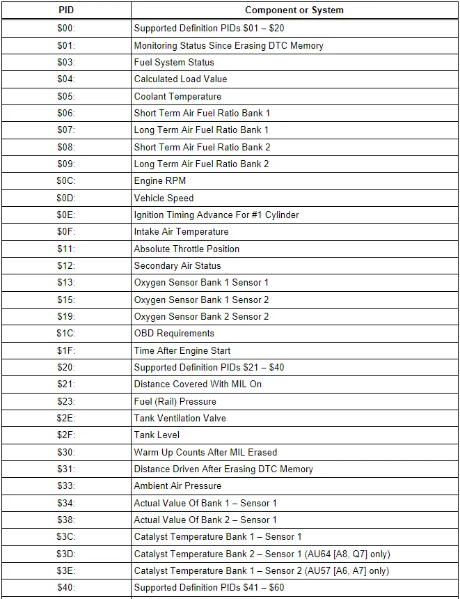
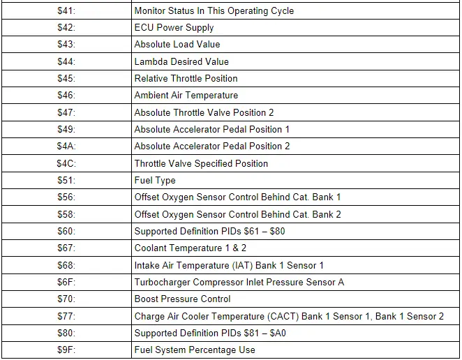
- From the following table, select the desired the "PID" that is to be monitored, e.g. "PID $05 Coolant temperature".
The current values of the component or system that is being monitored will be displayed on the scan tool screen.
- Switch the ignition off.
Diagnostic Mode 02 - Read Operating Conditions
When an emissions-related fault (pending DTC, visible in mode 07) is first detected, operating conditions are stored. Mode 02 makes it possible to access this freeze frame data as soon as this fault is shown in mode 03. Each control module only shows freeze frame data for one fault via mode 02. Therefore, there are two priority levels. If there is a malfunction with higher priority, the freeze frame data is overwritten.
- Fault with higher priority: Misfire malfunction or fuel trim malfunction.
- Fault with normal priority: All other emissions-related faults.
 Note
Note
Depending on scan tool and protocol used, the information in diagnostic mode 02 may be referred to by different names such as Test-ID (TID), Hex-ID, Component-ID (CID), or On-Board Diagnostic Monitor Identifier (OBDMID).
Procedure
- Connect the scan tool.
- Start the engine and run at idle.
 Note
Note
If the engine does not start, crank the engine using starter for at least 5 seconds, do not switch the ignition off afterward under any circumstances.
- Select "Diagnostic Mode 2: Obtain operating conditions.".
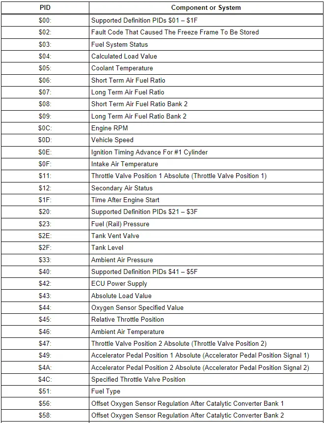
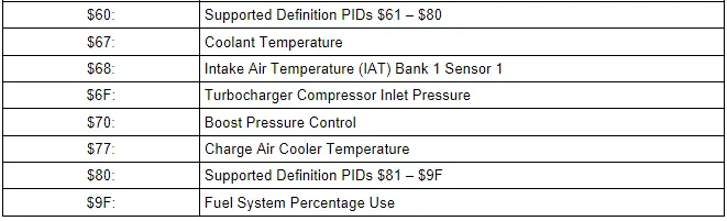
- From the following table, select the desired the "PID", e.g. "PID 05-Coolant temperature" that is to be monitored.
The current values of the component or system that is being monitored will be displayed on the scan tool screen.
- Switch the ignition off.
Diagnostic Mode 03 - Read DTC Memory
Diagnostic Mode 03 makes it possible to read emissions-related faults (confirmed DTCs; faults which have activated the MIL) in the ECM and in the TCM.
When the ECM recognizes an emissions-related fault in two consecutive drive cycles, it sends a request to the instrument cluster over the CAN to turn on the malfunction indicator lamp. If an electronic throttle malfunction is recognized, the ECM will send a request to the instrument cluster over the CAN to turn on the electronic power control warning lamp.
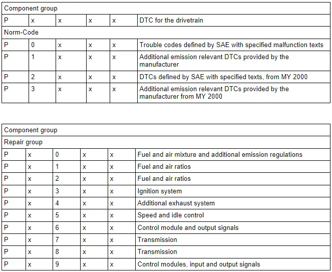
The DTCs are sorted by SAE code with the DTC tables consisting of a 5-digit alphanumeric value.
 Note
Note
Depending on scan tool and protocol used, diagnostic mode 03 and the information provided may be referred to by a different name.
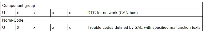
The following tables provide a breakdown and explanation of the DTC code.
P-Codes
U-Codes
Procedure
- Connect the scan tool.
- Switch the ignition to the ON position.
- Select Diagnostic Mode 03: Interrogating fault memory.
- The stored DTC or DTCs will be displayed on the scan tool screen.
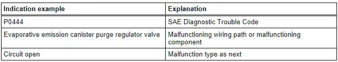
The following table is an example of the DTC information that may be displayed on the scan tool screen:
- Refer to the DTC tables below for the diagnostic repair procedures.
- Switch the ignition off.
Diagnostic Mode 04 - Erase DTC Memory
Diagnostic Mode 04 makes it possible to erase the DTC memory and to reset all emissions-related diagnostic data. In that way, all faults in the DTC memory in the ECM and TCM are erased. The adaptation values may also be reset.
Emissions-related diagnostic data includes (as applicable):
- - MIL Status
- - Number of DTCs
- - Readiness bits
- - Confirmed DTCs
- - Pending DTCs
- - DTC that belongs to freeze frame
- - Freeze frame data
- - Test results of specific diagnostic functions
- - Distance driven with "MIL ON"
- - Number of warm-up cycles after erasing the DTC memory
- - Distance driven after erasing the DTC memory
- - Misfire counter
 Note
Note
Depending on scan tool and protocol used, diagnostic mode 04 and the information provided may be referred to by a different name.
Procedure
- Connect the scan tool.
- Switch the ignition on.
- Select Diagnostic Mode 03: Interrogating fault memory.
- Then select Mode 4: Reset/delete diagnostic data.
The scan tool will display: Diagnostic data are being erased.
- Switch the ignition off.
Diagnostic Mode 05 - Read Oxygen Sensor Monitoring Test Results
 Note
Note
Mode 05 may not be supported on all systems. On systems where Diagnostic Mode 05 is not supported, refer to Diagnostic Mode 6 for oxygen sensor monitoring test results.
Test Requirements
- No Test requirements are available for this powertrain.
Function Test
- No Function Tests are available for this powertrain.

