Audi Q7: Diagnostic Mode 07 - Read Faults Detected During the Current or Last Driving Cycle
Mode 07 makes it possible to check emissions-related faults which appeared during the current or last driving cycle (pending DTCs).
A pending DTC is saved the first time a fault is detected (output via Mode 07).
- If the fault is detected again by the end of the following driving cycle, a confirmed DTC is entered (output via Mode 03) and the MIL is activated.
- If this malfunction is not detected again by the end of the following driving cycle, the corresponding pending code will be deleted at the end of the driving cycle.
 Note
Note
Depending on scan tool and protocol used, some of the information provided may be referred to by a different name.
Procedure
- Connect the scan tool.
- Start the engine and run at idle.
 Note
Note
If the engine does not start, crank the engine using starter for at least 5 seconds. Do not switch the ignition off afterward.
- Select Mode 7: Check test results of components that are continuously monitored.
The number of pending DTCs or 0 malfunctions detected will be displayed on the scan tool screen.
- Refer to the DTC tables below for the diagnostic repair procedures.
- → Chapter "Engine Control Module, 2015 MY"
- → Chapter "Engine Control Module, 2016 MY"
- → Chapter "Engine Control Module, 2017 MY (Q7)"
- Switch the ignition off.
Diagnostic Mode 08 - Request Control of On-Board System, Test or Component
Diagnostic Mode 08 is used to control the operation of an on-board system, test or component. A Mode 8 service can be used to turn on-board system ON or OFF, or to cycle an on-board system, test or component on or off for a specific period of time. The service can also be used to request system status or to report test results.
Test requirements
- No DTCs stored in the DTC memory.
- Intake Air Temperature (IAT) maximum 60º C.
- Coolant temperature 80 -110º C.
- Throttle valve angle 12.0 - 16.0%.
Function test
 Note
Note
If the accelerator pedal is depressed during the test, the test will be aborted.
- Connect the scan tool.
- Start the engine and run at idle for at least 15 minutes.
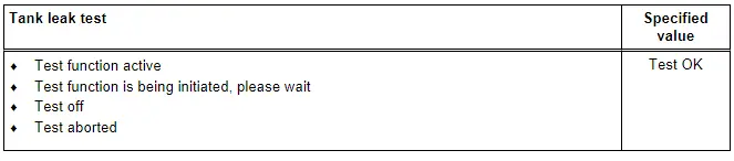
- Select "Mode 8: Tank Leak Test".
- Select "Test-ID 01: Tank Leak Test".
- Check the specified value of the tank leak test at idle.
- The following will be displayed on the scan tool screen:
- Switch the ignition off.
If the specified result is obtained:
System OK.
If the specified result is not obtained:
- Repeat the tank leak test, switch the ignition off and start the engine again and let run for 15 minutes at idle.
- Switch the ignition off.
If the specified result is again not obtained:
- A leak may be present. Refer to → Chapter "EVAP System, Checking for Leaks".
Diagnostic Mode 09 - Read Vehicle Information
Diagnostic Mode 09 makes it possible to access vehicle-specific information from the ECM and the TCM (where applicable).
 Note
Note
Depending on scan tool and protocol used, Diagnostic Mode 09 and the information provided may be referred to by a different name.
Test requirement
- No DTCs stored in the DTC memory.
Procedure
- Connect the scan tool.
- Switch the ignition on.
- Select Mode 09: Vehicle information.
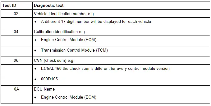
- Select the desired Test-ID.
- The information requested will be displayed on the scan tool screen.
The following table is a numerical list of all Test-IDs that may be selected.
- Switch the ignition off.

