Audi Q7: Diagnostic Mode 06 - Read Test Results for Specific Diagnostic Functions, 2017 MY (Q7)
Diagnostic Mode 06 makes it possible to retrieve test results for special components and systems which are continuously or not continuously monitored. If the diagnosis of a system is complete, the diagnostic result and the corresponding thresholds are saved and displayed in mode 06. This data remains saved (even with the ignition off) until either new diagnostic results become available or the DTC memory is erased.
The min & max values for each individual test in Mode 06 represent the min & max operating values for a properly operating system. This data is provided to the individual aftermarket scan tool companies for development of their scan tool. Depending on the scan tool being used, the min & max values shown may vary, or be rounded up or down to the nearest decimal point depending on the aftermarket scan tool company's development process.
For example; GST manual documentation will show the value as 0.3499 (units) while the scan tool will display the same value as 0.35 (units).
Depending on the scan tool and protocol used, the information displayed in Diagnostic Mode 06 may be referred to by different names such as Test-ID (TID), Hex-ID, Component-ID (CID), On-Board Diagnostic Monitor Identifier (OBDMID), or contain no name at all and may be referenced by only a number.
Test requirements
- Exhaust system must be properly sealed between catalytic converter and cylinder head.
- No DTC's in the DTC memory.
- Coolant temperature at least 80º C.
Work procedure
- Connect the scan tool.
- Start the engine and let run at idle speed.
- Select Mode 6: Check test the results of components that are not continuously monitored.
Select the desired Test-ID.
The current minimum and maximum values will be displayed on the scan tool screen.
The following table is a numerical list of all"Test-IDs" that may be selected.
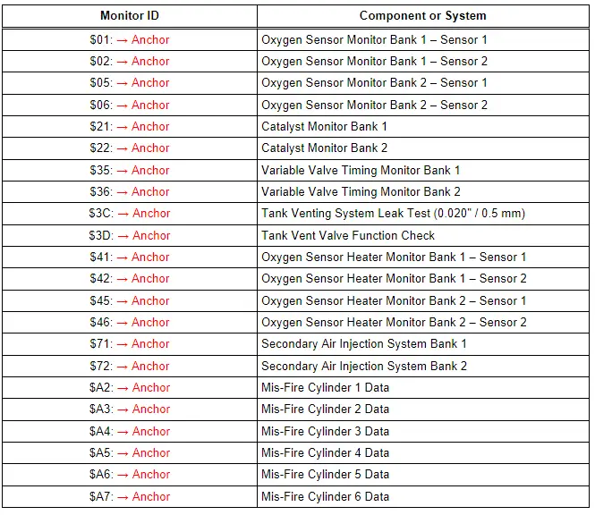
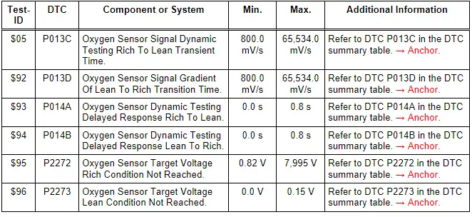
Monitor $01: Oxygen Sensor Monitor Bank 1 - Sensor 1
- Connect the scan tool.
- Start the engine and let run at idle speed.
- Select "Diagnostic Mode 6: Check test the results of components that are not continuously monitored".
Select "Monitor $01".
- Select the desired "Test-ID" or "Hex-ID".
- Check specified values at idle.
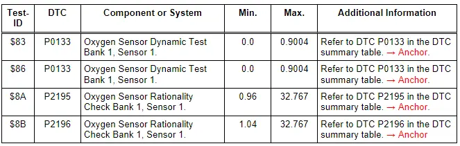
- If any component or system fails to meet the specified values, refer to Diagnostic "Mode 03: Interrogating Fault Memory" to check for stored DTC's or the corresponding diagnostic repair procedure → Chapter "Diagnostic Mode 03 - Read DTC Memory".
- Switch the ignition off.
Monitor $02: Oxygen Sensor Monitor Bank 1 - Sensor 2
- Connect the scan tool.
- Start the engine and let run at idle speed.
- Select "Diagnostic Mode 6: Check test the results of components that are not continuously monitored".
Select "Monitor $02".
- Select the desired "Test-ID" or "Hex-ID".
- Check specified values at idle.
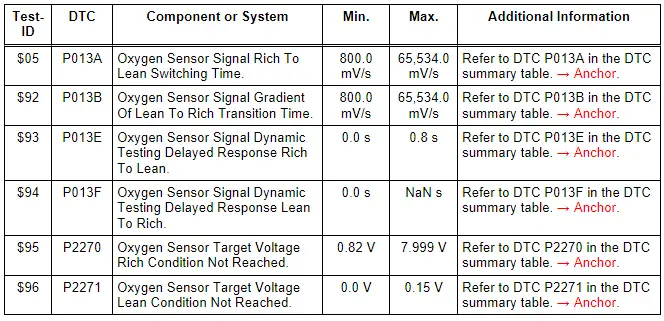
- If any component or system fails to meet the specified values, refer to Diagnostic "Mode 03: Interrogating Fault Memory" to check for stored DTC's or the corresponding diagnostic repair procedure → Chapter "Diagnostic Mode 03 - Read DTC Memory".
- Switch the ignition off.
Monitor $05: Oxygen Sensor Monitor Bank 2 - Sensor 1
- Connect the scan tool.
- Start the engine and let run at idle speed.
- Select "Diagnostic Mode 6: Check test the results of components that are not continuously monitored".
Select "Monitor $05".
- Select the desired "Test-ID" or "Hex-ID".
- Check specified values at idle.
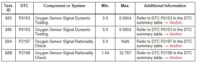
- If any component or system fails to meet the specified values, refer to Diagnostic "Mode 03: Interrogating Fault Memory" to check for stored DTC's or the corresponding diagnostic repair procedure → Chapter "Diagnostic Mode 03 - Read DTC Memory".
- Switch the ignition off.
Monitor $06: Oxygen Sensor Monitor Bank 2 - Sensor 2
- Connect the scan tool.
- Start the engine and let run at idle speed.
- Select "Diagnostic Mode 6: Check test the results of components that are not continuously monitored".
Select "Monitor $06".
- Select the desired "Test-ID" or "Hex-ID".
- Check specified values at idle.
- If any component or system fails to meet the specified values, refer to Diagnostic "Mode 03: Interrogating Fault Memory" to check for stored DTC's or the corresponding diagnostic repair procedure → Chapter "Diagnostic Mode 03 - Read DTC Memory".
- Switch the ignition off.
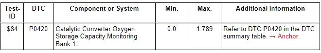
Monitor $21: Catalyst Monitor Bank 1
- Connect the scan tool.
- Start the engine and let run at idle speed.
- Select "Diagnostic Mode 6: Check test the results of components that are not continuously monitored".
Select "Monitor $21".
- Select the desired "Test-ID" or "Hex-ID".
- Check specified values at idle.
- If any component or system fails to meet the specified values, refer to Diagnostic "Mode 03: Interrogating Fault Memory" to check for stored DTC's or the corresponding diagnostic repair procedure → Chapter "Diagnostic Mode 03 - Read DTC Memory".
- Switch the ignition off.
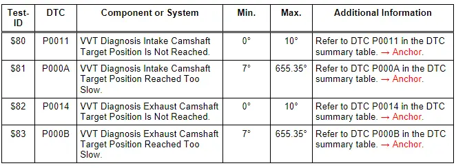
Monitor $35: Variable Valve Timing Monitor Bank 1
- Connect the scan tool.
- Start the engine and let run at idle speed.
- Select "Diagnostic Mode 6: Check test the results of components that are not continuously monitored".
Select "Monitor $35".
- Select the desired "Test-ID" or "Hex-ID".
- Check specified values at idle.
- If any component or system fails to meet the specified values, refer to Diagnostic "Mode 03: Interrogating Fault Memory" to check for stored DTC's or the corresponding diagnostic repair procedure → Chapter "Diagnostic Mode 03 - Read DTC Memory".
- Switch the ignition off.
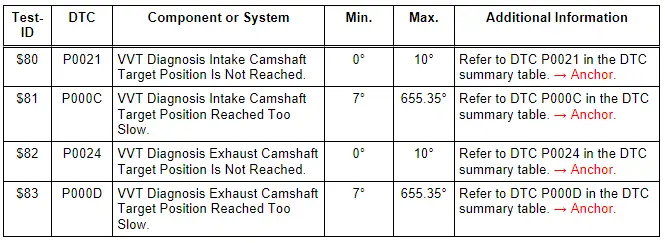
Monitor $36: Variable Valve Timing Monitor Bank 2
- Connect the scan tool.
- Start the engine and let run at idle speed.
- Select "Diagnostic Mode 6: Check test the results of components that are not continuously monitored".
Select "Monitor $36".
- Select the desired "Test-ID" or "Hex-ID".
- Check specified values at idle.
- If any component or system fails to meet the specified values, refer to Diagnostic "Mode 03: Interrogating Fault Memory" to check for stored DTC's or the corresponding diagnostic repair procedure → Chapter "Diagnostic Mode 03 - Read DTC Memory".
- Switch the ignition off.
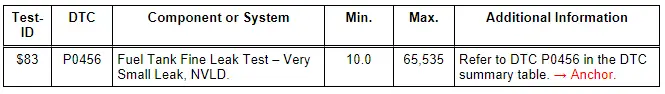
Monitor $3C: Tank Venting System Leak Test (0.020" / 0.5 mm)
- Connect the scan tool.
- Start the engine and let run at idle speed.
- Select "Diagnostic Mode 6: Check test the results of components that are not continuously monitored".
Select "Monitor $3C".
- Select the desired "Test-ID" or "Hex-ID".
- Check specified values at idle.
- If any component or system fails to meet the specified values, refer to Diagnostic "Mode 03: Interrogating Fault Memory" to check for stored DTC's or the corresponding diagnostic repair procedure → Chapter "Diagnostic Mode 03 - Read DTC Memory".
- Switch the ignition off.
- End of diagnosis.
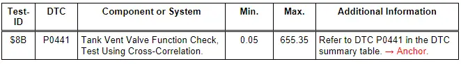
Monitor $3D: Tank Vent Valve Function Check
- Connect the scan tool.
- Start the engine and let run at idle speed.
- Select "Diagnostic Mode 6: Check test the results of components that are not continuously monitored".
Select "Monitor $3D".
- Select the desired "Test-ID" or "Hex-ID".
- Check specified values at idle.
- If any component or system fails to meet the specified values, refer to Diagnostic "Mode 03: Interrogating Fault Memory" to check for stored DTC's or the corresponding diagnostic repair procedure → Chapter "Diagnostic Mode 03 - Read DTC Memory".
- Switch the ignition off.
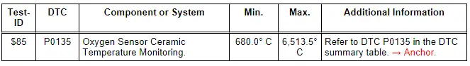
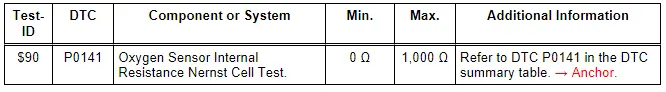
Monitor $41: Oxygen Sensor Heater Monitor Bank 1 - Sensor 1
- Connect the scan tool.
- Start the engine and let run at idle speed.
- Select "Diagnostic Mode 6: Check test the results of components that are not continuously monitored".
Select "Monitor $41".
- Select the desired "Test-ID" or "Hex-ID".
- Check specified values at idle.
- If any component or system fails to meet the specified values, refer to Diagnostic "Mode 03: Interrogating Fault Memory" to check for stored DTC's or the corresponding diagnostic repair procedure → Chapter "Diagnostic Mode 03 - Read DTC Memory".
- Switch the ignition off.
Monitor $42: Oxygen Sensor Heater Monitor Bank 1 - Sensor 2
- Connect the scan tool.
- Start the engine and let run at idle speed.
- Select "Diagnostic Mode 6: Check test the results of components that are not continuously monitored".
Select "Monitor $42".
- Select the desired "Test-ID" or "Hex-ID".
- Check specified values at idle.
- If any component or system fails to meet the specified values, refer to Diagnostic "Mode 03: Interrogating Fault Memory" to check for stored DTC's or the corresponding diagnostic repair procedure → Chapter "Diagnostic Mode 03 - Read DTC Memory".
- Switch the ignition off.
Monitor $45: Oxygen Sensor Heater Monitor Bank 2 - Sensor 1
- Connect the scan tool.
- Start the engine and let run at idle speed.
- Select "Diagnostic Mode 6: Check test the results of components that are not continuously monitored".
Select "Monitor $45".
- Select the desired "Test-ID" or "Hex-ID".
- Check specified values at idle.
- If any component or system fails to meet the specified values, refer to Diagnostic "Mode 03: Interrogating Fault Memory" to check for stored DTC's or the corresponding diagnostic repair procedure → Chapter "Diagnostic Mode 03 - Read DTC Memory".
- Switch the ignition off.
Monitor $46: Oxygen Sensor Heater Monitor Bank 2 - Sensor 2
- Connect the scan tool.
- Start the engine and let run at idle speed.
- Select "Diagnostic Mode 6: Check test the results of components that are not continuously monitored".
Select "Monitor $46".
- Select the desired "Test-ID" or "Hex-ID".
- Check specified values at idle.
- If any component or system fails to meet the specified values, refer to Diagnostic "Mode 03: Interrogating Fault Memory" to check for stored DTC's or the corresponding diagnostic repair procedure → Chapter "Diagnostic Mode 03 - Read DTC Memory".
- Switch the ignition off.
Monitor $71 : Secondary Air Injection System Bank 1
- Connect the scan tool.
- Start the engine and let run at idle speed.
- Select "Diagnostic Mode 6: Check test the results of components that are not continuously monitored".
Select "Monitor $71".
- Select the desired "Test-ID" or "Hex-ID".
- Check specified values at idle.
- If any component or system fails to meet the specified values, refer to Diagnostic "Mode 03: Interrogating Fault Memory" to check for stored DTC's or the corresponding diagnostic repair procedure → Chapter "Diagnostic Mode 03 - Read DTC Memory".
- Switch the ignition off.
Monitor $72: Secondary Air Injection System Bank 2
- Connect the scan tool.
- Start the engine and let run at idle speed.
- Select "Diagnostic Mode 6: Check test the results of components that are not continuously monitored".
Select "Monitor $72".
- Select the desired "Test-ID" or "Hex-ID".
- Check specified values at idle.
- If any component or system fails to meet the specified values, refer to Diagnostic "Mode 03: Interrogating Fault Memory" to check for stored DTC's or the corresponding diagnostic repair procedure → Chapter "Diagnostic Mode 03 - Read DTC Memory".
- Switch the ignition off.
Monitor $A2: Mis-Fire Cylinder 1 Data
- Connect the scan tool.
- Start the engine and let run at idle speed.
- Select "Diagnostic Mode 6: Check test the results of components that are not continuously monitored".
Select "Monitor $A2".
- Select the desired "Test-ID" or "Hex-ID".
- Check specified values at idle.

- If any component or system fails to meet the specified values, refer to Diagnostic "Mode 03: Interrogating Fault Memory" to check for stored DTC's or the corresponding diagnostic repair procedure → Chapter "Diagnostic Mode 03 - Read DTC Memory".
- Switch the ignition off.
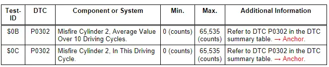
Monitor $A3: Mis-Fire Cylinder 2 Data
- Connect the scan tool.
- Start the engine and let run at idle speed.
- Select "Diagnostic Mode 6: Check test the results of components that are not continuously monitored".
Select "Monitor $A3".
- Select the desired "Test-ID" or "Hex-ID".
- Check specified values at idle.
- If any component or system fails to meet the specified values, refer to Diagnostic "Mode 03: Interrogating Fault Memory" to check for stored DTC's or the corresponding diagnostic repair procedure → Chapter "Diagnostic Mode 03 - Read DTC Memory".
- Switch the ignition off.
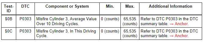
Monitor $A4: Mis-Fire Cylinder 3 Data
- Connect the scan tool.
- Start the engine and let run at idle speed.
- Select "Diagnostic Mode 6: Check test the results of components that are not continuously monitored".
Select "Monitor $A4".
- Select the desired "Test-ID" or "Hex-ID".
- Check specified values at idle.
- If any component or system fails to meet the specified values, refer to Diagnostic "Mode 03: Interrogating Fault Memory" to check for stored DTC's or the corresponding diagnostic repair procedure → Chapter "Diagnostic Mode 03 - Read DTC Memory".
- Switch the ignition off.
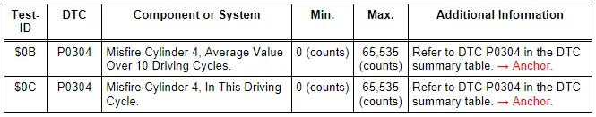
Monitor $A5: Mis-Fire Cylinder 4 Data
- Connect the scan tool.
- Start the engine and let run at idle speed.
- Select "Diagnostic Mode 6: Check test the results of components that are not continuously monitored".
Select "Monitor $A5 ".
- Select the desired "Test-ID" or "Hex-ID".
- Check specified values at idle.
- If any component or system fails to meet the specified values, refer to Diagnostic "Mode 03: Interrogating Fault Memory" to check for stored DTC's or the corresponding diagnostic repair procedure → Chapter "Diagnostic Mode 03 - Read DTC Memory".
- Switch the ignition off.
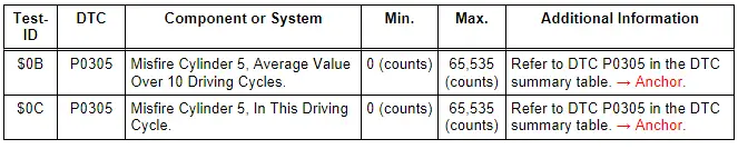
Monitor $A6: Mis-Fire Cylinder 5 Data
- Connect the scan tool.
- Start the engine and let run at idle speed.
- Select "Diagnostic Mode 6: Check test the results of components that are not continuously monitored".
Select "Monitor $A6 ".
- Select the desired "Test-ID" or "Hex-ID".
- Check specified values at idle.
- If any component or system fails to meet the specified values, refer to Diagnostic "Mode 03: Interrogating Fault Memory" to check for stored DTC's or the corresponding diagnostic repair procedure → Chapter "Diagnostic Mode 03 - Read DTC Memory".
- Switch the ignition off.
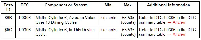
Monitor $A7: Mis-Fire Cylinder 6 Data
- Connect the scan tool.
- Start the engine and let run at idle speed.
- Select "Diagnostic Mode 6: Check test the results of components that are not continuously monitored".
Select "Monitor $A7"
- Select the desired "Test-ID" or "Hex-ID".
- Check specified values at idle.
- If any component or system fails to meet the specified values, refer to Diagnostic "Mode 03: Interrogating Fault Memory" to check for stored DTC's or the corresponding diagnostic repair procedure → Chapter "Diagnostic Mode 03 - Read DTC Memory".
- Switch the ignition off.

