Audi Q7: Accelerator Pedal Module - GX2-, Checking
Audi Q7 (4M) 2016-2025 Workshop Manual / Engine / Generic Scan Tool / Diagnosis and Testing / Accelerator Pedal Module - GX2-, Checking
General Description
The Accelerator Pedal Position Sensor -G79- and Accelerator Pedal Position Sensor 2 -G185- are combined in one component and integrated into the Accelerator Pedal Module - GX2-. They are used to detect the position of the accelerator pedal throughout the entire adjustment range. The Engine Control Module - J623- detects the driver's request from these signals and uses them to calculate the injection quantity and EPC throttle valve operation.
The Accelerator Pedal Module - GX2- contains the following components:
- Accelerator Pedal Position Sensor -G79-
- Accelerator Pedal Position Sensor 2 -G185-
The Accelerator Pedal Module - GX2- components cannot be serviced separately, and they must be serviced as a unit.
Special tools and workshop equipment required
- Multimeter.
- Wiring Diagram.
- Scan Tool.
Test requirements
- Fuses OK.
- Battery voltage OK.
- Switch OFF all electrical and electronic accessories.
- Vehicles with automatic transmission, ensure the selector lever position is in "P".
- Vehicles with manual transmission, ensure the shifter lever position is in "N" with the parking brake applied.
- Coolant temperature: ≥ 80º C.
- Observe all safety precautions: → Chapter "Safety Precautions".
- View clean working conditions: → Chapter "Clean Working Conditions".
- For Hybrid vehicles, refer to: → Chapter "High Voltage System General Warnings".
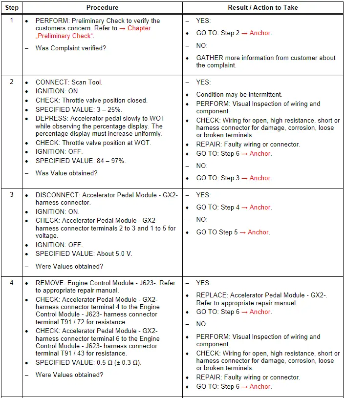
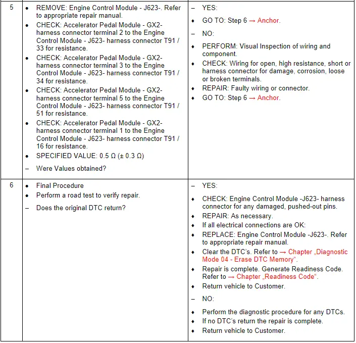
Test Procedure