Audi Q7: Windshield Defogger Control Module -J505-, Removing and Installing
 Note
Note
Information regarding the Windshield Defogger Control Module -J505- and activation of the Windshield Defogger -Z2-. Refer to → Chapter "Windshield Defogger".
Removing
- Turn off the ignition.
- Remove the glove compartment. Refer to → Body Interior; Rep. Gr.68; Storage Compartments and Covers; Glove Compartment, Removing and Installing.
- Disconnect the ground cable from the battery with the ignition switched off. Refer to → Electrical Equipment; Rep. Gr.27; Battery; Battery, Disconnecting and Connecting.
 Caution
Risk of short circuit when disconnecting the power supply to the Windshield Defogger Control Module -J505-.
- Disconnect the battery ground cable with the ignition switched off.
- Remove the retainer in the power supply to the Windshield Defogger Control Module -J505-. Refer to → Wiring diagrams, Troubleshooting & Component locations.
- Before loosening the hex nut check with a voltage tester that there is no more voltage.
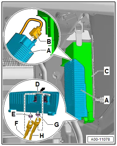
- Release and open the clamp protection -D-.
- Mark the wires -F and H- for reinstallation.
- Remove the nuts -E and G- and free up the wires.
- Isolate the positive cable -H- due to the risk of a short circuit.
- Release the catch and remove the Windshield Defogger Control Module -J505--A- from the bracket -C- downward.
- Release and remove the connector -B-.
Installing
Installation is done is reverse order, observe the following:
- Attach the wires -F and H- according to the marks.
- Nuts -E and G- (M6 threads), tightening specification: 7.5 Nm.
Sunlight Photo Sensor -G107-, Removing and Installing
 Note
Note
There are different versions of the Sunlight Photo Sensor -G107-. Therefore, ensure that the allocation is correct. Refer to the Parts Catalog. Should a Sunlight Photo Sensor -G107- be installed that is not intended for this vehicle (it emits a different signal than the one intended in this Front A/C Display Control Head -E87- A/C control head), the Front A/C Display Control Head -E87- cannot evaluate the signal from the Sunlight Photo Sensor -G107- and the A/C system regulation is faulty. Refer to Vehicle Diagnostic Tester in the "Guided Fault Finding" function.
Removing
- Turn off the ignition.
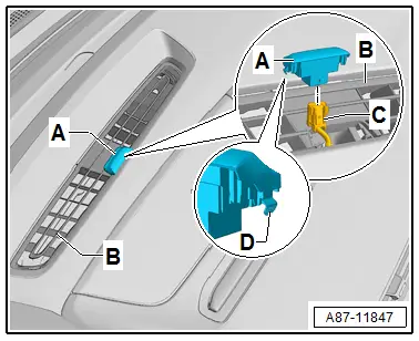
- Using a small screwdriver, carefully pry the Sunlight Photo Sensor -G107--A- off the defroster vent -B- (for windshield).
 Note
Note
- Do not damage the cover surface of the Sunlight Photo Sensor -G107--A- and the defroster vent -B-.
- The Sunlight Photo Sensor -G107--A- is held with tabs -D- of the defroster vent -B-.
- Disengage and remove connector -C-.
Installing
Install in reverse order of removal. Note the following:
- After installing retrieve the Front A/C Display Control Head -E87- DTC memory and if necessary delete the displayed error. Refer to Vehicle Diagnostic Tester in the "Guided Fault Finding" function.

