Audi Q7: Headlamp Washer System
Overview - Headlamp Washer System
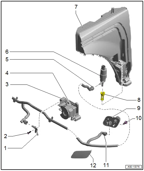
1 - Night Vision System Camera -R212- Washer Nozzle
- Removing and installing. Refer to → Chapter "Night Vision System Camera -R212- Washer Nozzle, Removing and Installing".
2 - Bolt
- 2.5 Nm
- Quantity: 2
3 - Mount
- For Night Vision System Camera -R212-
4 - Night Vision System Camera -R212-
5 - Washer Fluid Hose
- To the washer nozzles
6 - Headlamp Washer Pump -V11-
- Removing and installing. Refer to → Chapter "Headlamp Washer Pump -V11-, Removing and Installing".
7 - Washer Fluid Reservoir
8 - Grommet
- For Headlamp Washer Pump -V11-
9 - Washer Nozzle
- Removing and installing. Refer to → Chapter "Headlamp Washer System Washer Nozzle, Removing and Installing".
- Are already adjusted by the manufacturer and must not be adjusted after installation.
10 - Bolt
- 2.5 Nm
- Quantity: 2
11 - Washer Fluid Hose
- To the washer nozzles
12 - Cover
- For the headlamp washer system washer nozzle
Headlamp Washer Pump -V11-, Removing and Installing
Special tools and workshop equipment required
- Drip Tray
Removing
- Remove the washer fluid reservoir until the headlamp washer pump is accessible. Refer to → Chapter "Washer Fluid Reservoir, Removing and Installing".
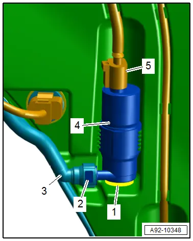
- Disconnect the connector -5-.
- Place a drip tray under the washer fluid reservoir.
- Press the release button -2- and remove the washer fluid hose -3- from the headlamp washer pump -4-.
- Remove the headlamp washer pump upward and out of the washer fluid reservoir.
Installing
Install in the reverse order of removal while noting the following:
- Check the grommet -1- for damage.
Washer Nozzles, Removing and Installing
Headlamp Washer System Washer Nozzle, Removing and Installing
Special tools and workshop equipment required
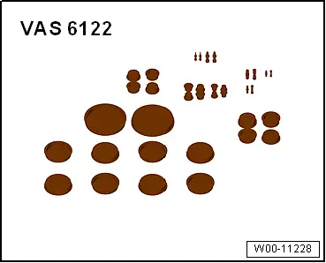
- Engine Bung Set -VAS6122-
- Drip Tray
Removing
- Remove the cover for the headlamp washer system spray nozzle. Refer to → Body Exterior; Rep. Gr.63; Front Bumper; Attachments, Removing and Installing.
- Remove the front wheel spoiler. Refer to → Body Exterior; Rep. Gr.66; Wheel Housing Liner; Overview - Front Wheel Housing Liner.
- Vehicles with side auxiliary cooler: Remove the front bumper cover. Refer to → Body Exterior; Rep. Gr.63; Front Bumper; Bumper Cover, Removing and Installing.
- Remove the bolts -arrows-.
- Remove the spray nozzle -1- toward the rear.
- Place the drip tray under the washer nozzle.
- Remove the washer fluid hose -3- by pressing the release buttons -1-.
- Seal off the hose coupling with clean plugs from the Engine Bung Set -VAS6122-.
Installing
Install in reverse order of removal.
Tightening Specifications
- Refer to → Chapter "Overview - Headlamp Washer System"
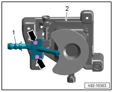
Night Vision System Camera -R212- Washer Nozzle, Removing and Installing
Removing
- Remove the mount for the Night Vision System Camera -R212-. Refer to → Communication; Rep. Gr.91; Infrared System.
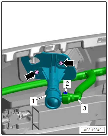
- Remove the bolts -arrows-.
- Remove the washer nozzle -1- from the mount -2-.
Installing
Install in the reverse order of removal while noting the following:
- If the mount is removed, the Night Vision System Camera -R212- must be recalibrated. Refer to → Suspension, Wheels, Steering; Rep. Gr.44; Infrared System; Infrared System, Calibrating.
Tightening Specifications
- Refer to → Chapter "Overview - Headlamp Washer System"
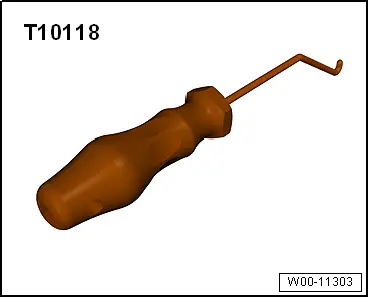
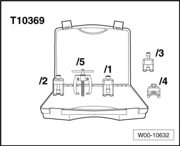
Special Tools
Special tools and workshop equipment required
- Elbow Assembly Tool -T10118-
- Puller - Wiper Arm Kit -T10369-
- Engine Bung Set -VAS6122-
- Drip Tray