Audi Q7: Electrically-Driven A/C Compressor
 WARNING
Risk of short circuit
The A/C compressor works with up to 288 volts at 800 to 8,600 RPM.
Do not touch the A/C compressor when the ignition is turned on or when the drive machines are activated because of the short circuit risk.
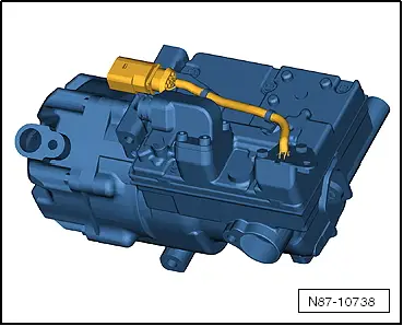
- The A/C compressor extracts the refrigerant gas from the evaporator, compresses it and relays it to the condenser.
- The electric motor for the A/C compressor is powered with voltage from the Electric Drive Power and Control Electronics -JX1-.
- The A/C Compressor Control Module -J842- integrated in the A/C compressor controls the rotation and thereby the output for the A/C compressor (Electrical A/C Compressor -V470-) corresponding with the Data bus receiving requirements. Use the Vehicle Diagnostic Tester in the "Guided Fault Finding" Function for the A/C System and the Battery Regulation.
- There is no A/C Compressor Regulator Valve -N280- installed in the electrically-driven A/C compressor.
- Check the attachment points on the A/C compressor and the bracket prior to installation. The contact surfaces must be clean and free of rust and grease. Otherwise, repair the contact surfaces with the Contact Surface Cleaning Set -VAS6410-. Refer to → Electrical Equipment General Information; Rep. Gr.97; Wire and Connector Repair.
 Note
Note
- Check the amount of refrigerant oil in the new A/C compressor if the A/C Compressor Control Module -J842- is faulty. Do not flush the refrigerant circuit with R134a.
- The A/C Compressor Control Module -J842- and the Electrical A/C Compressor -V470- are one component and are currently not able to be separated.
- There is no A/C Compressor Regulator Valve -N280- installed in the electrically driven A/C compressor. The A/C compressor output is regulated externally by the A/C compressor speed. Refer to → Wiring diagrams, Troubleshooting & Component locations and use the Vehicle Diagnostic Tester in the "Guided Fault Finding" Function for the A/C System and the Battery Regulation.
- The electrically-driven A/C compressor functions according to the principle of a spiral charger (similar to a G-charger).
- The A/C compressor contains refrigerant oil, which can be mixed with refrigerant R134a under any temperature.
- The data plate lists the type of refrigerant required for the A/C compressor.
- The installed electronics are controlled by the speed of the A/C compressor power output (and the pressure on the low pressure side) within the specified range (control characteristic).
- The engine should only be started if the refrigerant circuit is completely assembled.
- The A/C compressor is equipped with a protected oil supply, this prevents A/C compressor damage in the event that the system is empty. This means that approximately 40 to 50 cm3 of refrigerant oil remains in the A/C compressor.
- The electrically-driven A/C compressor has a relief valve like the mechanically-driven A/C compressor.
- Hybrid drive on vehicles with battery cooling is only possible with a fully charged A/C system in which there are no stored errors. Use the Vehicle Diagnostic Tester in the "Guided Fault Finding" Function for the A/C System and the Battery Regulation.
- After the installation of the electrically-driven A/C compressor and the subsequent filling of the refrigerant circuit, start the A/C compressor for the first time using the "compressor intake" function for the basic setting. The A/C compressor may otherwise become damaged if before installation, refrigerant oil was improperly stored in the A/C compressor compression chamber. Use the Vehicle Diagnostic Tester in the "Guided Fault Finding" Function for the A/C System and the Battery Regulation.
- Only activate the electrically-driven A/C compressor when the refrigerant circuit is filled. The A/C compressor may become damaged if the A/C compressor is run when the refrigerant circuit is empty. Use the Vehicle Diagnostic Tester in the "Guided Fault Finding" Function for the A/C System and the Battery Regulation.
Condenser
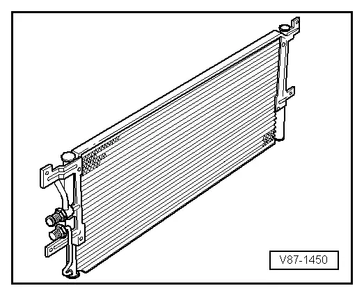
The condenser conducts heat from compressed refrigerant gas to the ambient air.
This condenses the refrigerant gas to fluid.
 Note
Note
- Depending on the version of the refrigerant circuit, the receiver/dryer is installed (integrated) either on the condenser or inside the condenser. Refer to → Heating, Ventilation and Air Conditioning; Rep. Gr.87; System Overview - Refrigerant Circuit (vehicle-specific repair manual) and the Parts Catalog.
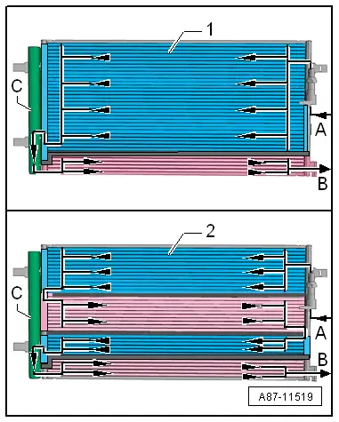
- The condenser is available in different versions and can be differentiated only by the part number on the outside. For version -1-, the condenser is divided into two areas "2 way condenser". For version -2-, the condenser is divided into four areas "4 way condenser".
- This illustration shows a condenser with the receiver/dryer -C- installed.
- The gaseous refrigerant enters at the connection -A- into the condenser. The refrigerant is then cooled inside the condenser and becomes fluid.
- The liquid refrigerant collects in the receiver/dryer -C- (with dryer) and flows through the lower cooling area towards the connection -B-.
- Depending on the design of the condenser (interior volumes, delivery flow, etc.), the amount of the refrigerant that is needed to fill the refrigerant circuit may vary. Therefore always be sure of the correct version and allocation for the condenser. Refer to → Chapter "Refrigerant R134a Capacities" and the Parts Catalog.
Evaporator
The evaporator is available in different versions. Depending on the version and the function, the necessary heat energy of the air flow (for example, an evaporator in the A/C unit or in the battery cooling module) or flowing coolant (for example near the high voltage battery heat exchanger) is extracted for refrigerant evaporation. Refer to → Heating, Ventilation and Air Conditioning; Rep. Gr.87; System Overview - Refrigerant Circuit (vehicle-specific repair manual).
 Note
Note
Two versions of evaporator are described.
Evaporator in A/C Unit (or in Battery Cooling Module)
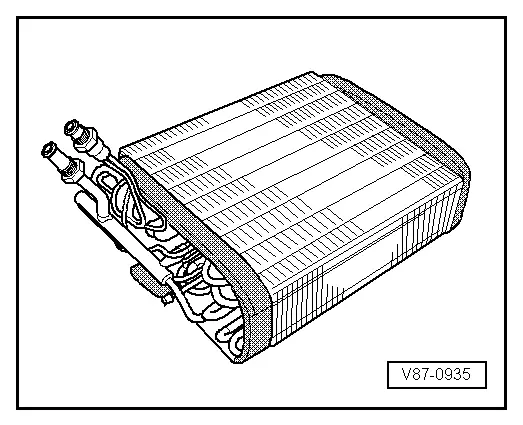
The fluid refrigerant evaporates in the evaporator pipe coils. The heat required for this is extracted from the air flowing on the evaporator ribbing. The air cools off. Refrigerant evaporates and is extracted with the absorbed heat by the A/C compressor.
A defined amount of refrigerant is supplied to the evaporator by a restrictor or expansion valve. In systems with expansion valve, the throughput is regulated so that only gaseous refrigerant escapes the evaporator outlet.
Evaporator/High Voltage Battery Heat Exchanger (Chiller)
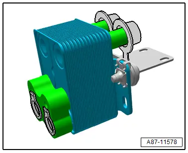
The liquid refrigerant evaporates in evaporator (heat exchanger). The heat required for this is extracted from the flowing refrigerant. The coolant cools, the refrigerant evaporates and is extracted with the absorbed heat by the A/C compressor.
A defined amount of refrigerant is supplied to the evaporator by a restrictor (or expansion valve) and a shut off valve. The throughput of the refrigerant (for example the coolant) is regulated so that only gaseous refrigerant escapes the evaporator outlet. Refer to → Heating, Ventilation and Air Conditioning; Rep. Gr.87; System Overview - Refrigerant Circuit (vehicle-specific repair manual).
Heat Pump Operation Heater Core
The gaseous or vaporous refrigerant that is compressed by the A/C compressor is liquefied in the A/C compressor -A- and at the same time released heat is transferred to the coolant flowing by. Refer to → Heating, Ventilation and Air Conditioning; Rep. Gr.87; Refrigerant Circuit; System Overview - Refrigerant Circuit.
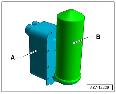
Fluid Collector
In some operating conditions (for example heat pump operation) the receiver/dryer (for example on the condenser) is not incorporated in the refrigerant circuit. The fluid collector -B- collects the refrigerant, and saves it if a specific quantity of refrigerant is not needed and directs it in an uninterrupted stream to the expansion valve (in front of the evaporator in the heater and A/C unit) or to the heat exchanger in the refrigerant circuit of the high-voltage system. Refer to → Heating, Ventilation and Air Conditioning; Rep. Gr.87; Refrigerant Circuit; System Overview - Refrigerant Circuit.

Reservoir
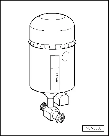
The reservoir collects the vaporized and gaseous mixture coming from the evaporator to ensure the compressor only receives gaseous refrigerant. Gaseous refrigerant is formed from the vapor.
The refrigerant oil flowing in the circuit is not retained in the reservoir as it has an oil drilling.
Moisture which has entered the refrigerant circuit during repairs will be collected by a filter (desiccant bag) in the reservoir.
Gaseous refrigerant is extracted with oil by the A/C compressor.
 Note
Note
- Replace the reservoir if refrigerant circuit has been open for a long time (beyond the normal repair time) and moisture has penetrated inside, or if required due to a specific complaint. Refer to → Chapter "Refrigerant Circuit Components, Replacing".
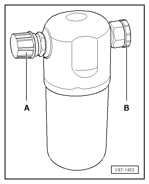
- Remove the sealing plugs -A- and -B- only immediately before installing.
- A desiccant bag in an unsealed reservoir is saturated with moisture after a short period of time and unusable.
- When installing, note arrow for direction of flow if necessary.
Restrictor
Restrictor in Front of the Evaporator
The restrictor creates a constriction. This restriction reduces the flow and creates high and low pressure sides in the refrigerant circuit. Before the restrictor the refrigerant which is under a higher pressure is warm. After the restrictor the refrigerant which is under a low pressure is cold. Before the restriction there is a strainer for contaminants and after the restriction there is a strainer, to atomize the refrigerant before it reaches the evaporator.
 Note
Note
- Arrow -A- on restrictor points to the evaporator.
- Replace after each opening of the circuit.
- There are different versions, therefore pay attention to the different customer service information sources. Refer to → Heating, Ventilation and Air Conditioning; Rep. Gr.87; System Overview - Refrigerant Circuit and (vehicle-specific repair manual) and to the Parts Catalog .
Restrictor in Front of the High Voltage Battery Heat Exchanger (Chiller)
The restrictor creates a constriction. This restriction reduces the flow and creates high and low pressure sides in the refrigerant circuit. Before the restrictor the refrigerant which is under a higher pressure is warm. After the restrictor the refrigerant which is under a low pressure is cold.
 Note
Note
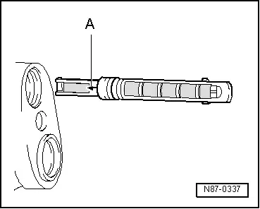
- The illustration shows a refrigerant line -A- with a fixed installed restrictor -B- (without a strainer)
- The diameter of the illustrated variable orifice -B- is approximately 0.7 mm. Depending on the version of the refrigerant line this constriction is either installed fixed in the refrigerant line or only inserted. For the inserted version a strainer for flowing deposits may be installed, which can be blocked by the variable orifice.
- Before installing check for debris and if necessary clean or replace.
- There are different versions, therefore pay attention to the different customer service information sources. Refer to → Heating, Ventilation and Air Conditioning; Rep. Gr.87; System Overview - Refrigerant Circuit and (vehicle-specific repair manual) and to the Parts Catalog.
Receiver/Dryer
The receiver/dryer collects the fluid drops and then directs them in an uninterrupted stream to the expansion valve. Moisture which has entered the refrigerant circuit during repairs will be collected by the desiccant bag in the receiver/dryer.
 Note
Note
- Replace the receiver/dryer if refrigerant circuit has been open for a long time (beyond the normal repair time) and moisture has penetrated inside, or if required due to a specific complaint. Refer to → Chapter "Refrigerant Circuit Components, Replacing".
- Only remove sealing plugs shortly before installation.
- A desiccant bag in an unsealed receiver/dryer becomes saturated with moisture after a short period of time and unusable.
- When installing, note arrow for direction of flow if necessary.
- Depending on the version of the refrigerant circuit, the receiver/dryer is also installed (integrated) either on the condenser or inside the condenser. Refer to → Heating, Ventilation and Air Conditioning; Rep. Gr.87; System Overview - Refrigerant Circuit (vehicle-specific repair manual) and the Parts Catalog.
- The procedure is different for each complaint depending on the version of the receiver/dryer and the dryer cartridge. If the receiver/dryer, for example, is attached to the condenser, then it can be replaced complete with the drying cartridge. If the receiver/dryer, for example, is inside the condenser, then the dryer cartridge, and any possible additional filters, can be replaced separately, on most versions. If the receiver/dryer is inside the condenser and there is absolutely no way to replace the reservoir or the dry cartridge individually, then the entire condenser must be replaced. Refer to →Heating, Ventilation and Air Conditioning; Rep. Gr.87 and →Heating, Ventilation and Air Conditioning; Rep. Gr.87 (vehicle-specific repair manual) and Parts Catalog.
- Depending on the construction of the refrigerant circuit, the receiver can also be secured onto the condenser. Refer to → Heating, Ventilation and Air Conditioning; Rep. Gr.87; System Overview - Refrigerant Circuit (vehicle-specific repair manual) and the Parts Catalog.
Expansion Valve
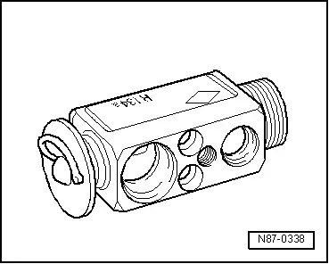
The expansion valve atomizes the streaming refrigerant and controls the flow quantity so that the vapor is gaseous only at the evaporator outlet, depending on the heat transmission.
 Note
Note
- Be sure to use the correct part number when replacing the expansion valve. Refer to the Parts Catalog.
- Different characteristic curves matched to the appropriate circuit. Refer to → Heating, Ventilation and Air Conditioning; Rep. Gr.87; System Overview - Refrigerant Circuit (vehicle-specific repair manual) and the Parts Catalog.
- Depending on the A/C compressor version, there may be a valve installed on the high pressure side of the A/C compressor, which prevents the liquid refrigerant from flowing back into the compressor once the A/C is turned off. If an A/C compressor with this valve is installed in a vehicle with a refrigerant circuit having an expansion valve, then it may take some time until the pressure in the high pressure side decreases (the expansion is cold and the pressure in the low pressure side quickly increases after it is turned off, the expansion valve closes and the refrigerant flows slowly into the low pressure side). If the A/C compressor is switched on, the pressure on the low pressure side goes down, the expansion valve open and the refrigerant can flow of the low pressure side.
Expansion Valve with Shut-Off Valve
 Note
Note
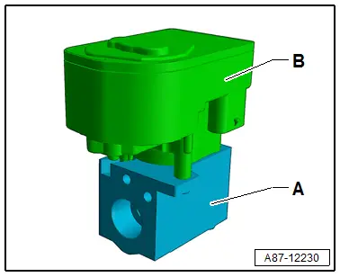
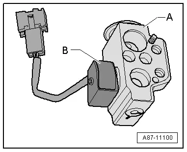
There are different versions of the shut-off valve with different functions and with different names. The following illustrated Hybrid Battery Refrigerant Shut-Off Valve 2 -N517- is for example installed on an Audi Q7 hybrid in the battery cooling module. Refer to → Heating, Ventilation and Air Conditioning; Rep. Gr.87; Refrigerant Circuit; System Overview - Refrigerant Circuit.
- The expansion valve -A- with the Hybrid Battery Refrigerant Shut-Off Valve 2 -N517--B- atomizes the streaming refrigerant and regulates the refrigerant flow rate to the evaporator in the battery cooling module for the Hybrid Battery Unit -AX1- so that the vapor becomes gaseous only at the evaporator output, depending on the heat transmission.
- If the Hybrid Battery Refrigerant Shut-Off Valve 2 -N517--B- is activated by the electronics and is open, it lets refrigerant flow through the expansion valve -A- to the evaporator in the battery cooling module.
- The expansion valve -A- with the Hybrid Battery Refrigerant Shut-Off Valve 2 -N517--B- is installed on vehicles with a battery cooling module. It is activated when the A/C system is in operation, if it is necessary to cool the Hybrid Battery Unit -AX1-.
- If the Hybrid Battery Refrigerant Shut-Off Valve 2 -N517--B- is activated by the electronics (for example, by the Battery Regulation Control Module -J840-), it is open and lets the refrigerant flow according to its control characteristic toward the evaporator in the battery cooling module.
- The Hybrid Battery Refrigerant Shut-Off Valve 2 -N517--B- attached to the expansion valve -A- is activated, for example, by the Battery Regulation Control Module -J840-. Refer to → Wiring diagrams, Troubleshooting & Component locations. Use the Vehicle Diagnostic Tester in the "Guided Fault Finding" Function for the A/C System and the Battery Regulation.
- If, for a vehicle with two evaporators (one in the A/C unit and one in the battery cooling module, for example on the Q5 Hybrid), the measured temperature on one of the evaporators corresponds to the specified value or the specified value falls short, but does not reach the required specified value on the other evaporator, the following adjustment is performed: the Battery Regulation Control Module -J840- activates the electric A/C compressor with increased speed (thereby increasing the A/C system cooling output and decreasing the pressure on the low pressure side as well as the evaporator temperature) via the Electric Drive Power and Control Electronics -JX1- and the A/C Compressor Control Module -J842-. If the specified value for the temperature falls short at one of the evaporators, the Battery Regulation Control Module -J840- activates the Hybrid Battery Refrigerant Shut-Off Valve 1 -N516- or the Hybrid Battery Refrigerant Shut-Off Valve 2 -N517-, so that the evaporator which is too cold is no longer supplied with refrigerant. Use the Vehicle Diagnostic Tester in the "Guided Fault Finding" Function for the A/C System.
Refrigerant Cut-Off Valve
 Note
Note
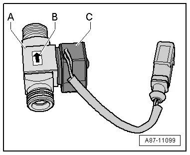
- There are different versions of the shut-off valve with different functions and with different names. The following illustrated Hybrid Battery Refrigerant Shut-Off Valve 1 -N516- is for example installed on an Audi Q7 hybrid. Refer to → Heating, Ventilation and Air Conditioning; Rep. Gr.87; Refrigerant Circuit; System Overview - Refrigerant Circuit.
- There are various designations, depending on the function and the vehicle. Refer to → Heating, Ventilation and Air Conditioning; Rep. Gr.87; Refrigerant Circuit; System Overview - Refrigerant Circuit.
Shut-Off Valve with Two Switching States (Open Or Closed)
- Hybrid Battery Refrigerant Shut-Off Valve 1 -N516- (for example the Audi Q5 Hybrid)
- Heater and A/C Unit Refrigerant Shut-Off Valve -N541- (for example on Audi A3 e-tron)
- High-Voltage Battery Heater Core Refrigerant Shut-Off Valve -N542- (for example on Audi A3 e-tron)
- Refrigerant Shut-Off Valve -V424- (for example on Audi Q7 e-tron)
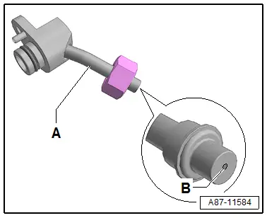
- If the shut-off -A- is not activated by the electronics, it is open and lets the refrigerant flow through to the evaporator in the A/C unit.
- The shut-off valve -A- is installed on vehicles with the battery cooling module. It is activated in hybrid mode when no A/C system operation is desired for the passenger compartment or for the Hybrid Battery Unit -AX1-, but is necessary for battery cooling.
- Observe the arrow -B- attached to the shut-off valve -A-, which shows the flow direction of the refrigerant (from the condenser to the evaporator in the A/C unit)
- The solenoid coil -C- attached to the shut-off valve is activated for example from the Battery Regulation Control Module -J840- → Wiring diagrams, Troubleshooting & Component locations. Use the Vehicle Diagnostic Tester in the "Guided Fault Finding" Function for the A/C System and the Battery Regulation.
- On a vehicle with two evaporators (one in the A/C unit and one for example on the Audi Q5 Hybrid) in the battery cooling module, if the measured temperature on one of the evaporators corresponds to the target value or the target value falls short, but does not reach the required target value on the other evaporator, the following adjustment is performed: the relevant control module (for example the Battery Regulation Control Module -J840- n the Audi Q5 hybrid) activates the electric A/C compressor with increased speed (thereby increasing the A/C cooling output and decreasing the pressure on the low pressure side as well as the evaporator temperature) via the A/C Compressor Control Module -J842-. If the target value falls short for the temperature of one of the evaporators, the relevant control module (for example the Battery Regulation Control Module -J840- on the Audi Q5 Hybrid the Hybrid Battery Refrigerant Shut-Off Valve 1 -N516- or the Hybrid Battery Refrigerant Shut-Off Valve 2 -N517-) activates so that the evaporator which is too cold is no longer supplied with refrigerant. Use the Vehicle Diagnostic Tester in the "Guided Fault Finding" Function for the A/C System and → Heating, Ventilation and Air Conditioning; Rep. Gr.87; System Overview - Refrigerant Circuit (for the specific vehicle).
Shut-Off Valve, which is Regulated via the Characteristic Curve
- Refrigerant Shut-Off Valve 2 -N640- through Refrigerant Shut-Off Valve 5 -N643- (for example on Audi Q7 e-tron)
- Refrigerant Expansion Valve 1 -N636- (for example on Audi Q7 e-tron)
- The shut-off valve -A- is activated via a step motor -B- from the respective control module via the characteristic curve (opened or closed).
- If the shut-off valve works as a regulator valve (for example on the Audi Q7 as Refrigerant Expansion Valve 1 -N636-) it is only open until the temperature for the heat exchanger is reached. Refer to → Heating, Ventilation and Air Conditioning; Rep. Gr.87; Refrigerant Circuit; System Overview - Refrigerant Circuit.
- Shut-off valves activated via the step motor do not have a specified resting position. For this reason before performing procedures on the refrigerant circuit it must be set to a specified position (open or closed). Refer to → Heating, Ventilation and Air Conditioning; Rep. Gr.87; Refrigerant Circuit; System Overview - Refrigerant Circuit.
- Depending on the design of the refrigerant circuit multiple shut-off valves can be combined in one valve block (for example on the Audi Q7 e-tron). Refer to → Heating, Ventilation and Air Conditioning; Rep. Gr.87; Refrigerant Circuit; System Overview - Refrigerant Circuit.
- The step motor is adapted and activated via the data wires (LIN Bus) from the respective control module according to its component location. Refer to → Heating, Ventilation and Air Conditioning; Rep. Gr.87; Refrigerant Circuit; System Overview - Refrigerant Circuit. Use the Vehicle Diagnostic Tester in the "Guided Fault Finding" function.