Audi Q7: Stabilizer Bar, Removing and Installing
Special tools and workshop equipment required
- Torque Wrench 1331 5-50Nm -VAG1331-
Removing
 Note
Note
During installation, all cable ties must be installed at the same location.
Before starting work:
- Versions with coil springs: determine the curb weight position. Refer to → Chapter "Wheel Bearing in Curb Weight Position, Lifting Vehicles with Coil Spring".
- Versions with air suspension: determine the standard vehicle height.. Refer to → Chapter "Wheel Bearing at Standard Vehicle Height, Lifting Vehicles with Air Suspension".
- Remove the front noise insulation. Refer to → Body Exterior; Rep. Gr.66; Noise Insulation; Noise Insulation, Removing and Installing.
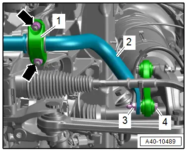
- Remove the left and right nuts -arrows- and -3-.
- Remove the left and right clamp -1- and the bolt -4-.
- Remove the stabilizer bar -2-.
Installing
Install in reverse order of removal and note the following:
 Note
Note
- There must be no grease on the stabilizer bar and rubber bushing.
- When the stud bolt for the clap has loosened tighten it until stop.
- Install the threaded connections for the stabilizer bar only until stop but do not yet tighten.
 Note
Note
Bonded rubber bushings have a limited range of motion. Only tighten suspension bolts when vehicle is in curb weight position or at standard vehicle height.
- Lifting the wheel bearing in curb weight position (refer to → Chapter "Wheel Bearing in Curb Weight Position, Lifting Vehicles with Coil Spring") or at standard vehicle height (refer to → Chapter "Wheel Bearing at Standard Vehicle Height, Lifting Vehicles with Air Suspension").
Tightening Specifications
- Refer to → Chapter "Overview - Subframe"
- Refer to → Body Exterior; Rep. Gr.66; Noise Insulation; Overview - Noise Insulation.
Coupling Rod, Removing and Installing
Special tools and workshop equipment required
- Torque Wrench 1332 40-200Nm -VAG1332-
- Engine and Gearbox Jack -VAS6931-
- Engine/Gearbox Jack Adapter - Wheel Hub Support -T10149-
Removing
Before starting work:
- Versions with coil springs: determine the curb weight position. Refer to → Chapter "Wheel Bearing in Curb Weight Position, Lifting Vehicles with Coil Spring".
- Versions with air suspension: determine the standard vehicle height. Refer to → Chapter "Wheel Bearing at Standard Vehicle Height, Lifting Vehicles with Air Suspension".
- Remove the front wheel. Refer to → Chapter.
- Turn the wheel hub, until the wheel bolt hole is on top.
 Caution
Risk of destroying the wheel bearing when installing the wheel bolt.
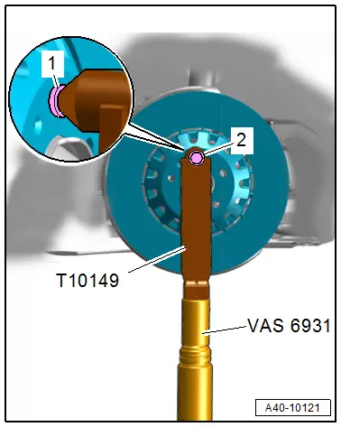
So that the installed wheel bolt cannot push against the wheel bearing, it (the bolt) must be installed with a washer inserted in between.
- Install the Engine/Gearbox Jack Adapter - Wheel Hub Support -T10149- with a wheel bolt -2- and inserted washer -1- on the wheel hub.
- Slightly lift the wheel bearing housing using the Engine/Gearbox Jack Adapter - Wheel Hub Support -T10149- with the Engine and Gearbox Jack -VAS6931- this allows the threaded connections to easily separate.
 WARNING
Risk of accident!
- Do not lift or lower the vehicle when the Engine and Gearbox Jack is under the vehicle.
- Do not leave the Engine and Gearbox Jack under the vehicle any longer than necessary.
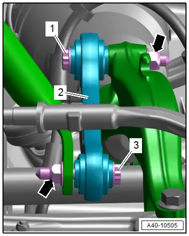
- Remove the nuts -arrows-.
- Remove the bolts -1 and 3- and coupling rod -2-.
 Note
Note
If necessary to remove the lower bolt push the front wheels accordingly.
Installing
Install in reverse order of removal and note the following:
- Install the threaded connections for the components with bonded rubber bushings only until stop but do not yet tighten.
 Note
Note
Bonded rubber bushings have a limited range of motion. Only tighten suspension bolts when vehicle is in curb weight position or at standard vehicle height.
- Lifting the wheel bearing in curb weight position (refer to → Chapter "Wheel Bearing in Curb Weight Position, Lifting Vehicles with Coil Spring") or at standard vehicle height (refer to → Chapter "Wheel Bearing at Standard Vehicle Height, Lifting Vehicles with Air Suspension").
Tightening Specifications
- Refer to → Chapter "Overview - Subframe"
- Refer to → Chapter "Wheels and Tires".
