Audi Q7: Engine, Installing
Special tools and workshop equipment required
- Torque Wrench 1332 Insert - Ring Wrench - 16mm -VAG1332/14-
- Clutch Module Transportation Lock -T40170-
 Caution
This procedure contains mandatory replaceable parts. Refer to component overview prior to starting procedure.
Mandatory Replacement Parts
- Bolts - Torque converter
- Bolt - Wheel bearing housing
- Bolts - Shock absorber fork
- Nuts - Shock absorber fork
- Nuts - Front Muffler
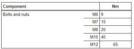
Tightening Specifications
 Note
Note
- The tightening specifications only apply to lightly greased, oiled, phosphated or blackened nuts and bolts.
- Additional lubricant such as engine oil or transmission fluid may be used, but do not use graphite lubricant.
- Do not use any parts that have had the lubrication removed.
- Tightening specification tolerance: +-15%
- Refer to → Chapter "Overview - Subframe Mount".
- Engine to transmission. Refer to → 8-Speed Automatic Transmission 0D5; Rep. Gr.37; Transmission, Removing and Installing; Transmission Tightening Specifications.
Procedure
 Note
Note
- Replace the bolts that were tightened with an additional turn after removing them.
- Replace the self-locking nuts and bolts, gaskets, seals and O-rings after removing.
- Only remove the plugs or caps just before installing the respective lines.
- The hose connections as well as air duct pipes and hoses must be free of oil and grease before installing.
- Secure all hose connections with hose clamps that match the ones used in series production. Refer to the Parts Catalog.
- To mount the air duct hoses on their connections securely, spray the bolts on the used clamps with rust remover before installing.
- During installation, all cable ties must be installed at the same location.
- Bonded rubber bushings have a limited range of rotation. Only tighten suspension threaded connections when vehicle is in curb weight position or in the control position.
- Secure the engine with the subframe on the Scissor Lift Table -VAS6131B-.
- Engine secured with the Engine Support -T10533/1- with -T10533/5-.
- Install the engine support and engine mount. Refer to → Chapter "Overview - Subframe Mount".
- Always clean the threaded holes for the engine/transmission threaded connection in the cylinder block using a thread tap before installing the transmission.
- The following preparations must be made before connecting the engine and transmission:
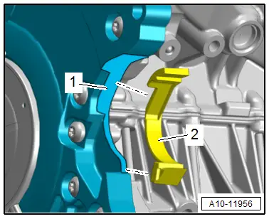
- Clean the contact surface -1- on the lower cover for the timing chain and on the locking piece -2- with Cleaning Solution -D 009 401 04-.
- Bond the locking piece with the lower cover for the timing chain.
- Bring the starter into the installation position.
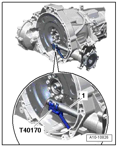
- Insert the Clutch Module Transportation Lock -T40170- in the transmission housing from below and secure it on the flange shaft -1-.
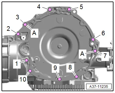
- Check if the alignment sleeves -A- for centering the engine and transmission are in the cylinder block and insert them if they are not.
- Inspect the aluminum bolts used to connect the engine to the transmission to check if they can be used again and mark them if necessary. Refer to → 8-Speed Automatic Transmission 0D5; Rep. Gr.37; Transmission, Removing and Installing; Transmission Tightening Specifications.
 Note
Note
When guiding together the engine and transmission make sure that the locking piece is seated correctly.
- Place the transmission on the engine and at the same time turn the bolt -1- for the starter.
- Install the bolts -2 to 11- all the way by hand.
- Tighten the bolts -1 to 11-.
- Remove the Clutch Module Transportation Lock -T40170- and Engine Support -T10533/1- with the -T10533/5-.
 Note
Note
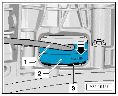
The following step is necessary to make sure the torque converter rests on the drive plate evenly and is not tilted.
- Press the torque converter -2- slightly in against the drive plate -3- in direction of -arrow- using an assembly lever -1-.
- Attach the torque converter to the drive plate as follows:
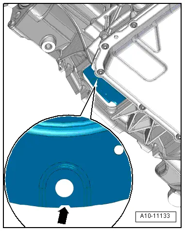
- Turn the torque converter so that hole next to the notch -arrow- is visible in the lower cut-out in the transmission housing as shown.
 Note
Note
There is only one notch on the circumference, so rotate the torque converter as needed.
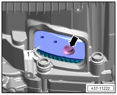
- Tighten the bolts -arrow- for the torque converter -1- that are accessible in this position. Refer to → 8-Speed Automatic Transmission; Rep. Gr.32; Torque Converter; Overview - Torque Converter.
 Note
Note
Use the Torque Wrench 1332 Insert - Ring Wrench - 16mm -VAG1332/14- to tighten the bolts.

- Rotate the crankshaft 180º further in direction of engine rotation in direction of -arrow- using the Crankshaft Socket -T40058- and ring wrench.
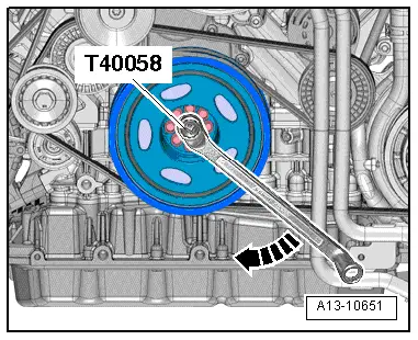
- Turn the crankshaft 60º farther and tighten the remaining five bolts to the tightening specification. Refer to → 8-Speed Automatic Transmission; Rep. Gr.32; Torque Converter; Overview - Torque Converter.
- Install the parking lock emergency release cable. Refer to → 8-Speed Automatic Transmission; Rep. Gr.37; Selector Mechanism.
- Install the ATF cooler. Refer to → 8-Speed Automatic Transmission; Rep. Gr.37; ATF Circuit; ATF Cooler, Removing and Installing.
- Install the drive axles. Refer to → Suspension, Wheels, Steering; Rep. Gr.40; Drive Axle; Overview - Drive Axle.
- Install the drive axle heat shields. Refer to → Suspension, Wheels, Steering; Rep. Gr.40; Drive Axle; Drive Axle Heat Shield, Removing and Installing.
- Install the catalytic converter. Refer to → Chapter "Overview - Muffler".
- Tighten the tunnel crossmember bolts. Refer to → 8-Speed Automatic Transmission; Rep. Gr.37; Subframe Mount; Overview - Subframe Mount.
- Remove the subframe locating pin. Refer to → Suspension, Wheels, Steering; Rep. Gr.40; Subframe; Subframe, Securing.
Installation is performed in reverse order of removal, while noting the following:
- Install the driveshaft. Refer to → Rear Final Drive; Rep. Gr.39; Driveshaft; Driveshaft, Removing and Installing.
- Install the front muffler. Refer to → Chapter "Front Muffler, Removing and Installing".
- Attach the steering intermediate shaft to the steering gear. Refer to → Suspension, Wheels, Steering; Rep. Gr.48; Steering Column; Steering Intermediate Shaft, Removing and Installing.
- Install the upper control arm and suspension strut. Refer to → Suspension, Wheels, Steering; Rep. Gr.40; Suspension Strut and Upper Control Arm; Overview - Suspension Strut and Upper Control Arm.
- Install the subframe crossbrace, shield and stabilizer bar. Refer to → Suspension, Wheels, Steering; Rep. Gr.40; Subframe; Overview - Subframe.
- Install the brake caliper. Refer to → Brake System; Rep. Gr.46; Front Brakes; Brake Caliper, Removing and Installing.
- Install the engine control module. Refer to → Chapter "Engine Control Module -J623-, Removing and Installing".
- Install the air filter housing. Refer to → Chapter "Air Filter Housing, Removing and Installing".
- Connections and wire routing. Refer to → Wiring diagrams, Troubleshooting & Component locations.
- Install the cable Terminal 30 Wire Junction 2 -TV22- and the cover for the engine compartment E-box. Refer to → Electrical Equipment; Rep. Gr.97; Relay Panels, Fuse Panels and E-Boxes; Component Location Overview - Relay Panels, Fuse Panels and E-Boxes.
- Install the A/C compressor. Refer to → Heating, Ventilation and Air Conditioning; Rep. Gr.87; A/C Compressor; A/C Compressor, Removing and Installing at Bracket.
- Install the ribbed belt. Refer to → Chapter "Ribbed Belt, Removing and Installing, Sub-Assembly Ribbed Belt".
- Install the ribbed belt tensioner for the supercharger. Refer to → Chapter "Ribbed Belt Tensioner, Removing and Installing, Supercharger Ribbed Belt".
- Install the front lower longitudinal member. Refer to → Body Exterior; Rep. Gr.50; Lock Carrier; Overview - Lock Carrier.
- Follow all steps after connecting the battery. Refer to → Electrical Equipment; Rep. Gr.27; Battery; Battery, Disconnecting and Connecting.
- Connect the fuel hose. Refer to → Fuel Supply System; Rep. Gr.20; Connector Couplings; Connector Couplings, Disconnecting.
 Caution
There is a risk of destroying the control modules due to excess voltage.
Do not use a charger to jump start.
- Fill with engine oil and check the oil level.
- Tighten the coolant pipes. Refer to → Chapter "Overview - Coolant Pipes".
- Connect the connection and coolant hoses with the connector coupling. Refer to → Fig. "Connect the Coolant Hose to the Connector Coupling".
 Note
Note
Used coolant cannot be used again.
- Fill with coolant.
- Install the wheel housing liners. Refer to → Body Exterior; Rep. Gr.66; Wheel Housing Liner; Overview - Front Wheel Housing Liner.
- Install the front wheels. Refer to → Suspension, Wheels, Steering; Rep. Gr.44; Wheels and Tires.
- Install the underbody trim panels. Refer to → Body Exterior; Rep. Gr.66; Underbody Trim Panel; Overview - Underbody Trim Panels.
- Install the noise insulations. Refer to → Body Exterior; Rep. Gr.66; Noise Insulation; Overview - Noise Insulation.

