Audi Q7: Subframe Mount
Overview - Subframe Mount
Engine Mount
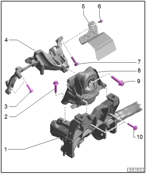
1 - Subframe
2 - Bolt
- 55 Nm
3 - Bolt
- 20 Nm
- M8
4 - Engine Support
- Removing and installing. Refer to → Chapter "Engine Support, Removing and Installing".
5 - Heat Shield
6 - Bolt
- 10 Nm
7 - Bolt
- 55 Nm
- M10
8 - Engine Mount
- With
- Left Electrohydraulic Engine Mount Solenoid Valve -N144-
- Right Electrohydraulic Engine Mount Solenoid Valve -N145-
- Removing and installing. Refer to → Chapter "Engine Mount, Removing and Installing".
9 - Bolt
- 90 Nm +90º
- Replace after removing
10 - Bolt
- 30 Nm
Transmission Mount
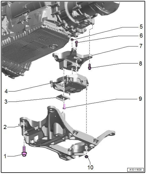
1 - Bolt
- Tightening specification. Refer to → 8-Speed Automatic Transmission; Rep. Gr.37; Subframe Mount; Overview - Subframe Mount.
2 - Tunnel Crossmember
- Removing and installing. Refer to → 8-Speed Automatic Transmission; Rep. Gr.37; Subframe Mount; Overview - Subframe Mount.
3 - Stop
- For the transmission mount
4 - Transmission Mount
- Removing and installing. Refer to → Chapter "Transmission Mount, Removing and Installing".
5 - Nut
- Tightening specification. Refer to → 8-Speed Automatic Transmission; Rep. Gr.37; Subframe Mount; Overview - Subframe Mount.
6 - Bolt
- Tightening specification. Refer to → 8-Speed Automatic Transmission; Rep. Gr.37; Subframe Mount; Overview - Subframe Mount.
7 - Transmission Support
- Removing and installing. Refer to → Chapter "Transmission Mount, Removing and Installing".
8, 9 - Bolt
- Tightening specification. Refer to → 8-Speed Automatic Transmission; Rep. Gr.37; Subframe Mount; Overview - Subframe Mount.
10 - Nut
- Tightening specification. Refer to → 8-Speed Automatic Transmission; Rep. Gr.37; Subframe Mount; Overview - Subframe Mount.
Engine, Supporting in Installation Position
Special tools and workshop equipment required
- Engine Support Bridge -10-222A-
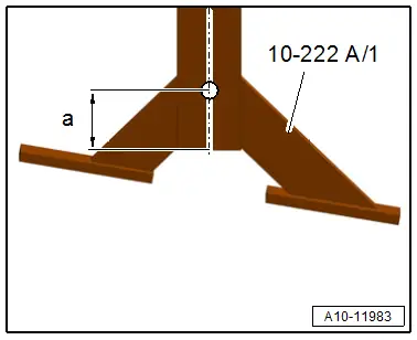
Tools, Preparing
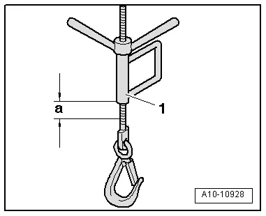
- Make a 11 mm diameter hole in both Engine Support Bridge - Engine Bracket -10-222A/1- as shown.
- Dimension -a- = 30 mm
Procedure
 WARNING
Risk of accident due to the engine weight shifting.
The transmission and tunnel crossmember must be installed for the support procedure described in the following.
- Remove the engine cover. Refer to → Chapter "Engine Cover, Removing and Installing".
- Remove the left and right headlamp cover. Refer to → Body Exterior; Rep. Gr.50; Lock Carrier; Overview - Lock Carrier.
- Position the Engine Support Bridge -10-222A- on the left and right longitudinal member as shown.
- Tighten the Engine Support Bridge - Adapters -10-222A/34- on the Engine Support Bridge - Engine Bracket -10-222A/1- with the nut -2- at the same time the adapter must engage in the longitudinal member -1- as shown.
- Attach the spindles Engine Support Bridge - Spindle -10-222A/11- to the left and right engine lifting eyes.
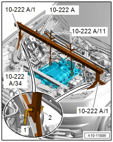
- Slightly pretension the engine with the spindle, do not lift.
Assembling
Assemble in the reverse order of removal. Note the following:
- Install the engine cover. Refer to → Chapter "Engine Cover, Removing and Installing".
Tightening Specifications
- Refer to → Chapter "Overview - Subframe Mount"
- Refer to → Body Exterior; Rep. Gr.50; Lock Carrier; Overview - Lock Carrier.
Engine Mount, Removing and Installing
Left Engine Mount, Removing and Installing
Removing
- Support the engine in the installation position. Refer to → Chapter "Engine, Supporting in Installation Position".
- Remove the front noise insulation. Refer to → Body Exterior; Rep. Gr.66; Noise Insulation; Noise Insulation, Removing and Installing.
- Remove the left front section of the wheel housing liner. Refer to → Body Exterior; Rep. Gr.66; Wheel Housing Liner; Front Wheel Housing Liner, Removing and Installing.
- Remove the ribbed belt from the A/C compressor belt pulley. Refer to → Chapter "Ribbed Belt, Removing and Installing, Sub-Assembly Ribbed Belt".
- Remove the lower left longitudinal member. Refer to → Body Exterior; Rep. Gr.50; Lock Carrier; Overview - Lock Carrier.
- Remove the A/C compressor from the bracket and tie it up on the left side. Refer to → Heating, Ventilation and Air Conditioning; Rep. Gr.87; A/C Compressor; A/C Compressor, Removing and Installing at Bracket.
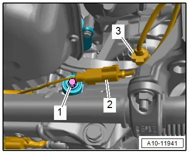
- Remove and disconnect the connector -3- for the Left Electrohydraulic Engine Mount Solenoid Valve -N144- from the bracket.
- Remove the connector -2- from the bracket, disconnect it and free up the wire.
 Note
Note
Ignore -1-.
- Remove the bolts -arrows- for the engine mount -1-.
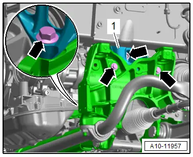
- Lift the engine using the Engine Support Bridge - Spindle -10-222A/11--1- to dimension -a-.
- Dimension -a- = approximately 15 mm.
- Remove the engine mount.
Installing
Install in reverse order of removal and note the following:
 Note
Note
Replace the bolts that were tightened with an additional turn after removing them.
- Install the ribbed belt. Refer to → Chapter "Ribbed Belt, Removing and Installing, Sub-Assembly Ribbed Belt".
Tightening Specifications
- Refer to → Chapter "Overview - Subframe Mount"
- Refer to → Heating, Ventilation and Air Conditioning; Rep. Gr.87; A/C Compressor; Overview - A/C Compressor Power Unit.
- Refer to → Body Exterior; Rep. Gr.50; Lock Carrier; Overview - Lock Carrier.
- Refer to → Body Exterior; Rep. Gr.66; Wheel Housing Liner; Overview - Front Wheel Housing Liner.
- Refer to → Body Exterior; Rep. Gr.66; Noise Insulation; Overview - Noise Insulation.
Right Engine Mount, Removing and Installing
Removing
- Lower the subframe. Refer to → Suspension, Wheels, Steering; Rep. Gr.40; Subframe; Subframe, Lowering.
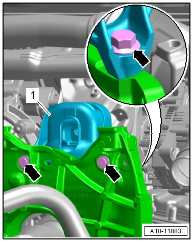
- Remove the bolts -arrows- and right engine mount -1-.
Installing
Install in reverse order of removal and note the following:
 Note
Note
Replace the bolts that were tightened with an additional turn after removing them.
- Install the subframe. Refer to → Suspension, Wheels, Steering; Rep. Gr.40; Subframe; Subframe, Lowering.
Tightening Specifications
- Refer to → Chapter "Overview - Subframe Mount"
Transmission Mount, Removing and Installing
Transmission Support with Transmission Mount, Removing and Installing
Removing
- Remove the tunnel crossmember. Refer to → 8-Speed Automatic Transmission; Rep. Gr.37; Subframe Mount; Overview - Subframe Mount.
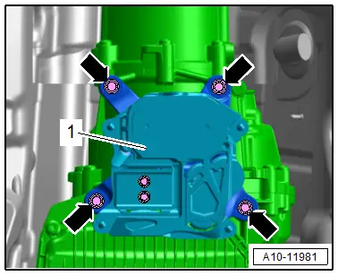
- Remove the bolts -arrows- and remove the transmission support with the transmission mount from the transmission.
Installing
Install in reverse order of removal.
Tightening Specifications
- Refer to → 8-Speed Automatic Transmission; Rep. Gr.37; Subframe Mount; Overview - Subframe Mount.
Transmission Mount, Removing and Installing
 Caution
This procedure contains mandatory replaceable parts. Refer to component overview prior to starting procedure.
Mandatory Replacement Parts
- Bolts - Transmission mount stop
Removing
- Remove the transmission support with the transmission mount. Refer to → Chapter "Transmission Support with Transmission Mount, Removing and Installing".
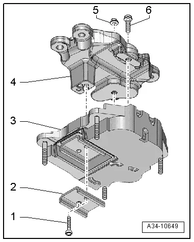
- Remove the bolts -1- and remove the stop -2- for the transmission mount.
- Remove the nut -5- and the bolt -6- and remove the transmission mount -3- from the transmission support -4-.
Installing
Install in reverse order of removal and note the following:
- Place the transmission support -4- on the transmission mount -3-.
- Tighten the nut -5- and bolt -6- hand-tight.
- Tighten the bolts -1- for the stop -2-.
- Tighten the nut -5- and bolt -6-.
- Install the transmission support with the transmission mount. Refer to → Chapter "Transmission Support with Transmission Mount, Removing and Installing".
Tightening Specifications
- Refer to → 8-Speed Automatic Transmission; Rep. Gr.37; Subframe Mount; Overview - Subframe Mount.

