Audi Q7: Front Brake Caliper, Removing and Installing
 Note
Note
In the following description the brake caliper is removed with the brake pads. The brake hose remains connected.
Special tools and workshop equipment required
- Torque Wrench 1332 40-200Nm -VAG1332-
 Caution
This procedure contains mandatory replaceable parts. Refer to component overview prior to starting procedure.
Mandatory Replacement Parts
- Brake Pad Wear Indicator Wire - Replace when pads are replaced.
- Bolt - Wheel Bearing Housing to Brake Caliper
- Brake Pad Retaining Plate - Replace when pads are replaced.
- Brake Pad Spring - Replace when pads are replaced.
Removing
 Caution
There is a risk of malfunctions.
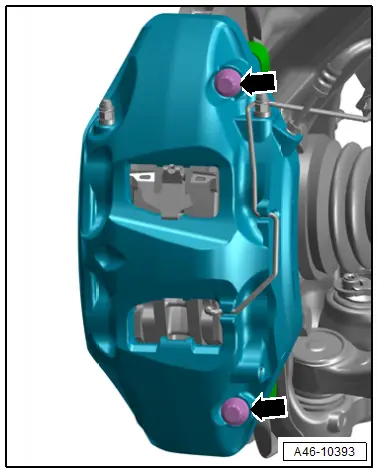
Do not loosen the bolts -arrows- on the brake caliper.
- Remove the front wheel. Refer to → Suspension, Wheels, Steering; Rep. Gr.44; Wheels and Tires.
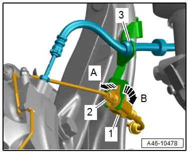
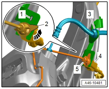
- Disconnect the connector -1- from the brake pad wear indicator.
- Release the connector -2- for the brake pad wear indicator from its bracket in direction of -arrow A- while turning it 90º at the same time in direction of -arrow B-.
- Free up the brake hose -3- on the bracket.
 Note
Note
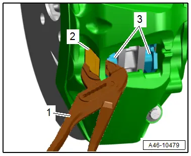
- For easier removal of the brake caliper from the brake rotor, push the brake pads -3- back lightly with pliers -1-.
- To prevent damage to the paint coat on the brake caliper, place a piece of rubber -2- between the pliers and brake caliper.
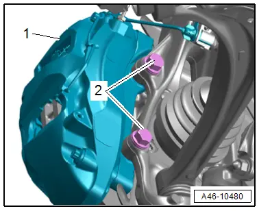
- Remove the bolts -2- and carefully remove the brake caliper -1- with the brake carrier and the installed brake pads from the brake rotor.

 Caution
Danger of damaging the brake hose.
- Do not let the brake caliper hang on the brake hose. Do not support the weight with the brake hose.
- Replace the brake hose if damaged.
Risk of damaging the brake caliper piston.
Do not press the brake pedal when the caliper is removed.
- Hang the brake caliper using a suitable wire.
Installing
Install in reverse order of removal and note the following:
 Note
Note
Replace the brake caliper bolts after disassembly.
 WARNING
Health Risk.
Do not blow out brake system with compressed air.
 Note
Note
Use only mineral spirits to clean the brake caliper.
- Clean the brake caliper.
- Slide the brake caliper -1- with the brake pads installed carefully over the brake rotor.
- Tighten the new bolts -2-.
 Note
Note
- Make sure the brake hose is routed correctly.
- Make sure the brake hose is not blocked, bent, twisted or rubbing against the vehicle.
- Secure the brake hose -3- to the bracket.
- Bring the connector -5- into its installed position and turn in the direction of -arrow- until the tab -2- engages in the opening -1- on the bracket.
- Connect the connector -4-.
 Note
Note
- Make sure that the connector and brake hose are routed correctly.
- Make sure the brake hose is not blocked, bent, twisted or rubbing against the vehicle.
 WARNING
Risk of accident!
- With the vehicle stationary, firmly press the brake pedal several times so that the brake pads in the operating condition properly set in their respective position.
- Make sure the brakes are working correctly before driving the vehicle for the first time.
Tightening Specifications
- Refer to → Chapter "Overview - Front Brakes"
- Refer to → Suspension, Wheels, Steering; Rep. Gr.44; Wheels and Tires.
Front Brake Caliper, Replacing
Special tools and workshop equipment required
- Torque Wrench 1332 40-200Nm -VAG1332-
- Torque Wrench 1410 -VAG1410-
- Brake Pedal Actuator -VAG1869/2-.
- Bleeder bottle from the Brake Charger/Bleeder Unit -VAS5234-
- M10 plug or M12 from the Assembly Part Set -5Q0 698 311-
 Caution
This procedure contains mandatory replaceable parts. Refer to component overview prior to starting procedure.
Mandatory Replacement Parts
- Brake Pad Wear Indicator Wire - Replace when pads are replaced.
- Brake Pad Retaining Plate - Replace when pads are replaced.
- Brake Pad Spring - Replace when pads are replaced.
- Bolt - Wheel Bearing Housing to Brake Caliper
 Note
Note
In the following description the brake caliper is removed and disconnected from the hydraulic system. The brake hose is removed.
Removing
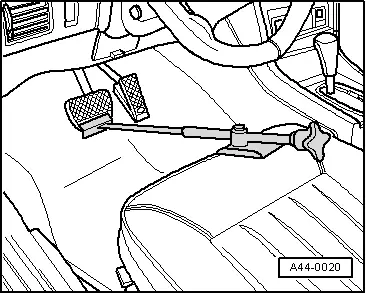
- Insert the Brake Pedal Actuator -VAG1869/2- between the brake pedal and driver seat. Preload the brake pedal at least 60 mm.
 Note
Note
By doing this, the valves in the brake master cylinder are closed and the brake fluid reservoir does not run empty.
- Remove the front wheel. Refer to → Suspension, Wheels, Steering; Rep. Gr.44; Wheels and Tires.
 WARNING
Risk of skin irritation.
To prevent skin contact with brake fluid, wear chemical resistant safety gloves.
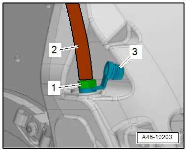
- Remove the protective cap -3- from the bleed screw -1-.
- Place the bleeder hose -2- of the bleeder bottle onto the bleed screw.
- Open the bleed screw to reduce the pressure in the hydraulic system.
- Close the bleed screw and remove the bleeder bottle.
 Note
Note
Do not remove the Brake Pedal Actuator -VAG1869/2-.
- To protect against escaping brake fluid, place a cloth under the separating point.
 WARNING
Malfunctions from contact with brake fluid with fluids containing mineral oils.
Brake fluid must never come into contact with fluids containing mineral oils (oil, gas, cleaning solutions). Safety gloves must be free of oil and grease.
Risk of damaging the painted surfaces.
Due to its caustic nature, brake fluid must also never be brought into contact with paint. Wash off any spilled brake fluid immediately with plenty of water.
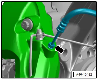
- Remove the union bolt -arrow- and remove the brake hose from the brake caliper.
- Immediately seal the open connection points with clean plugs from the Assembly Part Set -5Q0 698 311-.
- Remove the brake pads. Refer to → Chapter "Brake Pads, Removing and Installing".
Installing
Install in reverse order of removal and note the following:
- Install the brake pads. Refer to → Chapter "Brake Pads, Removing and Installing".
- Bring the brake hose into the installation position and tighten the union bolt -arrow-.
 Note
Note
- Make sure the brake hose is routed correctly.
- Make sure the brake hose is not blocked, bent, twisted or rubbing against the vehicle.
- Remove the Brake Pedal Actuator -VAG1869/2-.
- Only bleed the brakes on the wheel which the brake caliper and the brake hose was separated. Refer to → Chapter "Hydraulic System, Bleeding".
 Note
Note
If the brake pedal still feels "soft", completely bleed the brakes. Refer to → Chapter "Hydraulic System, Bleeding".
- Check brake fluid level, and fill if necessary.
 WARNING
Risk of accident!
- With the vehicle stationary, firmly press the brake pedal several times so that the brake pads in the operating condition properly set in their respective position.
- Make sure the brakes are working correctly before driving the vehicle for the first time.
Tightening Specifications
- Refer to → Chapter "Overview - Front Brakes"
- Refer to → Suspension, Wheels, Steering; Rep. Gr.44; Wheels and Tires.

