Audi Q7: Overview - Rear Brakes
Audi Q7 (4M) 2016-2025 Workshop Manual / Chassis / Brake System / Mechanical Components / Overview - Rear Brakes
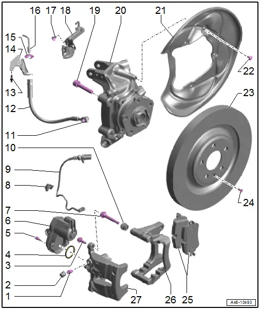
1 - Bleed Screw
- 10 Nm
- Before installing, thinly coat with Assembly Paste -G 052 150 A2-.
2 - Protective Cap
3 - Bolt
- 35 Nm
- Replace after removing
- When loosening and tightening, counterhold at the guide pin
- Self-locking
4 - Gasket
- Replace after removing
5 - Bolt
- 12 Nm
6 - Electro-Mechanical Parking Brake Motor
- Left Parking Brake Motor -V282-
- Right Parking Brake Motor -V283-
- Refer to → Chapter "Left and Right Parking Brake Motor - V282-/-V283-, Removing and Installing"
7 - Guide Pin
- Check ease of movement
8 - Clip
9 - Brake Pad Wear Indicator Wire
- With Left Rear Brake Pad Wear Sensor -G36-/Right Rear Brake Pad Wear Sensor -G37-
- For inner brake pad
- Replace when replacing the brake pads.
- Refer to → Chapter "Brake Pad Wear Indicator Wire, Removing and Installing"
10 - Protective Cap
- Replace if damaged
11 - Banjo Bolt
- 10 Nm +45º
- Permanent with gaskets
- Check for damage
- Replace together with the brake hose
- Clean any corrosion from the sealing surface on the brake caliper
12 - Brake Hose
- Observe correct routing: make sure the brake hose is not blocked, bent or rubbing against the vehicle
- Replace if damaged
- Make sure that lugs are properly seated in grooves in bracket.
13 - Rivet
14 - Bracket
- For the brake line/hose
- On the body
15 - Spring
- Replace if damaged
16 - Brake Line
- Tightening specification, brake line to brake hose, 14 Nm
17 - Bolt
- 8 Nm
18 - Bracket
- For brake hose
19 - Bolt
- 100 Nm +90º
- Replace after removing
- Self-locking
20 - Wheel Bearing Housing
21 - Brake Shield
- Refer to → Chapter "Brake Shield, Removing and Installing"
22 - Bolt
- 10 Nm
23 - Brake Rotor
- Do not use excessive force to separate the brake rotor from the wheel hub. Use rust remover, if necessary, otherwise the brake rotor could be damaged.
- Replace on both sides of axle if worn.
- Refer to → Chapter "Brake Rotor, Removing and Installing"
24 - Bolt
- 10 Nm
25 - Brake Pads
- Check the pad thickness.
- Refer to → Chapter "Brake Pads, Removing and Installing"
- Always replace on both axles.
- Installation position. Refer to → Fig. "Brake Pads Installation Position".
26 - Brake Carrier
- Delivered as an assembled replacement part with sufficient grease on the guide pins
- Refer to → Chapter "Brake Carrier, Removing and Installing"
- Clean the contact surfaces for the brake pads and thinly coat with Lithium Grease -G 052 150 A2-
27 - Brake Caliper
- Refer to → Chapter "Brake Caliper, Removing and Installing"
- Refer to → Chapter "Brake Caliper, Replacing"
- After servicing or replacing perform "Guided Fault Finding". Refer to Vehicle Diagnostic Tester.
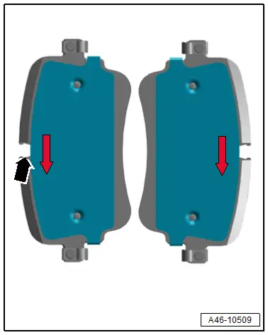
Brake Pads Installation Position
Version 1:
- In installed position, the arrow on the backing plate of the actual brake pad must point downward
 Note
Note
- The layout of the arrow is different depending on the manufacturer.
- The contact of the brake pad wear indicator is inserted in the opening -arrow- of the inner brake pad.
Version 2:
- Pay attention to the labeling on the backing plate of the brake pads.
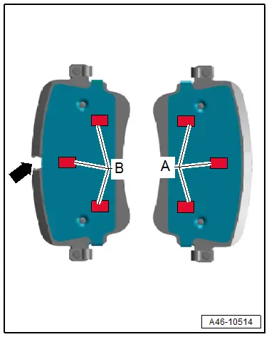
A - Outside
B - Inner
 Note
Note
Additionally the inner brake pad has an opening -arrow- for the contact of the brake pad wear indicator.

