Audi Q7: Fuel Delivery Unit - GX1-, Checking
General Description
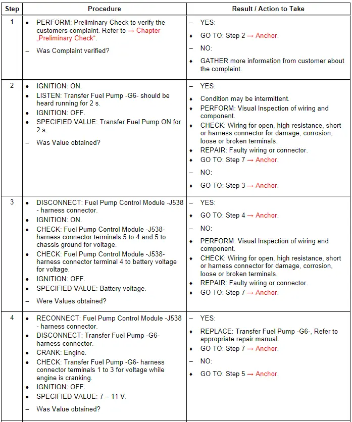
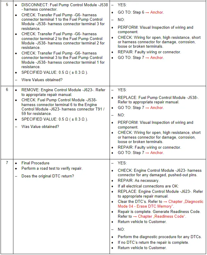
The Engine Control Module -J623- tells the Fuel Pump Control Module -J538- the demand needed for fuel volume and pressure and activates the Transfer Fuel Pump -G6-. The Transfer Fuel Pump -G6- transfers fuel to the rest of the fuel system, where it is monitored by the Engine Control Module -J623- through sensors, and controlled through regulators and/or metering valves.
Note the Fuel Delivery Unit -GX1- is also referred to as the Fuel Pump Control Module -J538-.
The Fuel Delivery Unit -GX1- contains the following components:
- Fuel Pump Control Module -J538-
- Transfer Fuel Pump -G6-
The Fuel Delivery Unit -GX1- components cannot be serviced separately, and they must be serviced as a unit.
Special tools and workshop equipment required
- Multimeter.
- Wiring Diagram.
- Scan Tool.
Test requirements
- Fuses OK.
- Battery voltage OK.
- Switch OFF all electrical and electronic accessories.
- Vehicles with automatic transmission, ensure the selector lever position is in "P".
- Vehicles with manual transmission, ensure the shifter lever position is in "N" with the parking brake applied.
- Coolant temperature: ≥ 80º C.
- Observe all safety precautions: → Chapter "Safety Precautions".
- View clean working conditions: → Chapter "Clean Working Conditions".
- For Hybrid vehicles, refer to: → Chapter "High Voltage System General Warnings".
Test Procedure
 Note
Note
When the door is opened or the Ignition is turned to the ON position the fuel pump is activated for 2 seconds to build up the pressure in the fuel system.
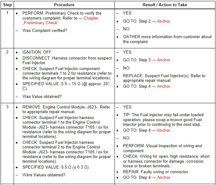
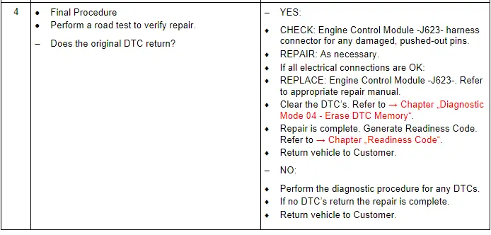
Fuel Injectors, Checking
General Description
The Fuel Injectors -N30, N31, N32, N33, N83, N84- are controlled by the Engine Control Module -J623- and are mounted normally in the cylinder head. The fuel injectors spray high-pressure, atomized fuel directly into the combustion chamber.
Special tools and workshop equipment required
- Multimeter.
- Wiring Diagram.
- Scan Tool.
- LED Test Lamp.
Test requirements
- Fuses OK.
- Battery voltage OK.
- Switch OFF all electrical and electronic accessories.
- Vehicles with automatic transmission, ensure the selector lever position is in "P".
- Vehicles with manual transmission, ensure the shifter lever position is in "N" with the parking brake applied.
- Coolant temperature: ≥ 80º C.
- Observe all safety precautions: → Chapter "Safety Precautions".
- View clean working conditions: → Chapter "Clean Working Conditions".
- For Hybrid vehicles, refer to: → Chapter "High Voltage System General Warnings".
Test Procedure
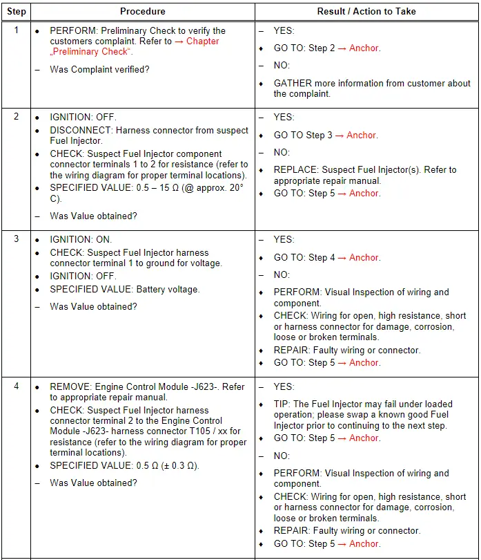
Fuel Injectors (2 [B Circuit]), Checking
General Description
The Fuel Injectors -N532, N533, N5324, N535, N536, N537- are powered by a Fuse Panel B -SB- fuse and are ground side switched/controlled by the Engine Control Module -J623-. They are mounted normally in the cylinder head. The fuel injectors spray high-pressure, atomized fuel directly into the combustion chamber.
Special tools and workshop equipment required
- Multimeter.
- Wiring Diagram.
- Scan Tool.
- LED Test Lamp.
Test requirements
- Fuses OK.
- Battery voltage OK.
- Switch OFF all electrical and electronic accessories.
- Vehicles with automatic transmission, ensure the selector lever position is in "P".
- Vehicles with manual transmission, ensure the shifter lever position is in "N" with the parking brake applied.
- Coolant temperature: ≥ 80º C.
- Observe all safety precautions: → Chapter "Safety Precautions".
- View clean working conditions: → Chapter "Clean Working Conditions".
- For Hybrid vehicles, refer to: → Chapter "High Voltage System General Warnings".
Test Procedure

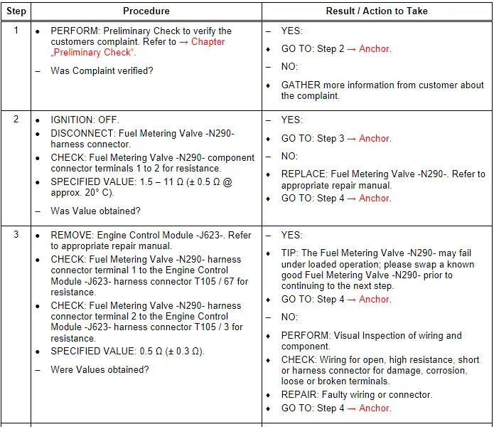
Fuel Metering Valve - N290-, Checking
General Description
The Engine Control Module -J623- regulates the Fuel Metering Valve -N290- directly at the High Pressure Fuel Pump to control the low pressure flow inside the High Pressure Fuel Pump.
Special tools and workshop equipment required
- Multimeter.
- Wiring Diagram.
- Scan Tool.
Test requirements
- Fuses OK.
- Battery voltage OK.
- Switch OFF all electrical and electronic accessories.
- Vehicles with automatic transmission, ensure the selector lever position is in "P".
- Vehicles with manual transmission, ensure the shifter lever position is in "N" with the parking brake applied.
- Coolant temperature: ≥ 80º C.
- Observe all safety precautions: → Chapter "Safety Precautions".
- View clean working conditions: → Chapter "Clean Working Conditions".
- For Hybrid vehicles, refer to: → Chapter "High Voltage System General Warnings".
Test Procedure
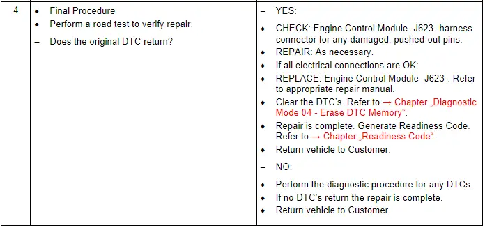
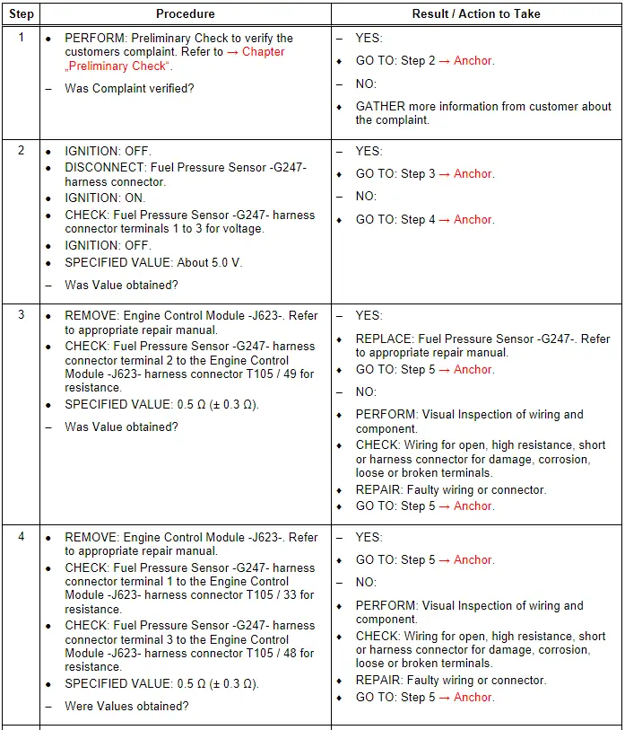
Fuel Pressure Sensor - G247-, Checking
General Description
The Fuel Pressure Sensor -G247- measures the fuel pressure in the high-pressure fuel system. The Engine Control Module -J623- analyzes the signal and regulates the fuel high pressure through the Fuel Metering Valve -N290- in the high-pressure pump.
Special tools and workshop equipment required
- Multimeter.
- Wiring Diagram.
- Scan Tool.
Test requirements
- Fuses OK.
- Battery voltage OK.
- Switch OFF all electrical and electronic accessories.
- Vehicles with automatic transmission, ensure the selector lever position is in "P".
- Vehicles with manual transmission, ensure the shifter lever position is in "N" with the parking brake applied.
- Coolant temperature: ≥ 80º C.
- Observe all safety precautions: → Chapter "Safety Precautions".
- View clean working conditions: → Chapter "Clean Working Conditions".
- For Hybrid vehicles, refer to: → Chapter "High Voltage System General Warnings".
Test Procedure
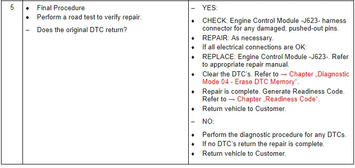
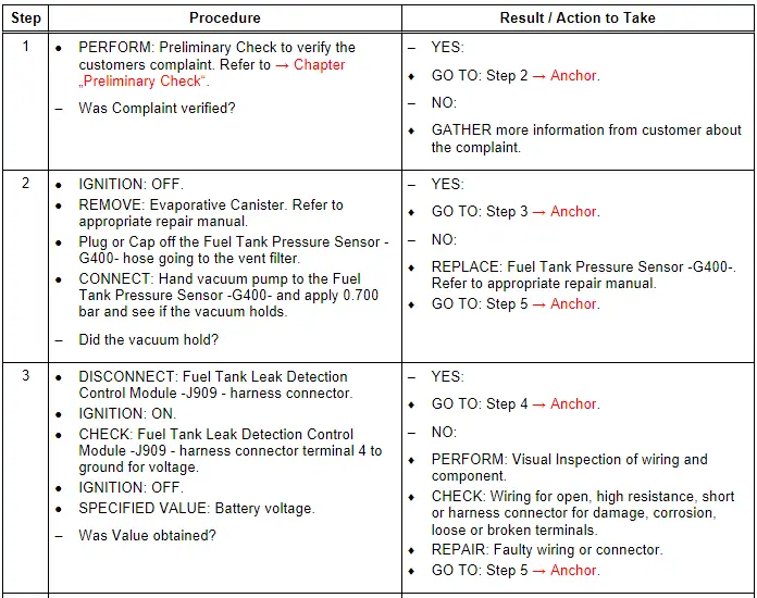
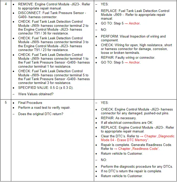
Fuel Tank Leak Detection Control Module - J909-, Checking
General Description
The system can test the evaporative system integrity by using natural vacuum after the engine is shut off. The Engine Control Module -J623- monitors the ability of the system to maintain vacuum through signals sent from the Fuel Tank Pressure Sensor -G400- and the Fuel Tank Leak Detection Control Module -J909-. If the vacuum remains for a specified period of time, then there are no evaporative leaks, and a PASS is reported by the Engine Control Module -J623-. If there is a leak, the system either will not achieve a vacuum, or a vacuum cannot be maintained. Usually a fault can only be detected after a cold start.
The Fuel Tank Leak Detection Control Module -J909- operates in conjunction with the following component:
- Fuel Tank Pressure Sensor -G400-
Special tools and workshop equipment required
- Multimeter.
- Wiring Diagram.
- Scan Tool.
- Hand Vacuum pump.
- Evap Smoke Tester.
Test requirements
- Fuses OK.
- Battery voltage OK.
- Switch OFF all electrical and electronic accessories.
- Vehicles with automatic transmission, ensure the selector lever position is in "P".
- Vehicles with manual transmission, ensure the shifter lever position is in "N" with the parking brake applied.
- Coolant temperature: ≥ 80º C.
- Observe all safety precautions: → Chapter "Safety Precautions".
- View clean working conditions: → Chapter "Clean Working Conditions".
- For Hybrid vehicles, refer to: → Chapter "High Voltage System General Warnings".
Test Procedure
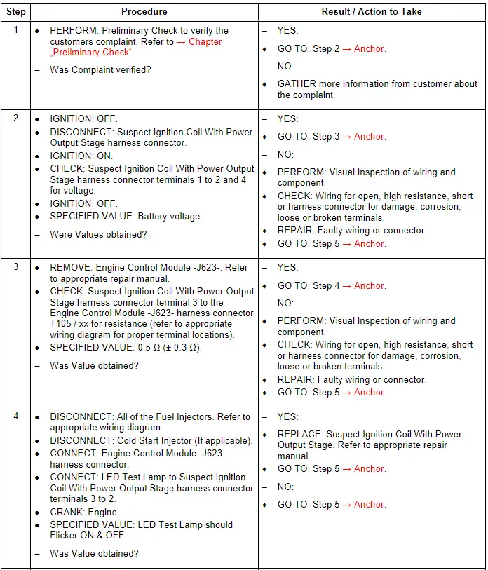
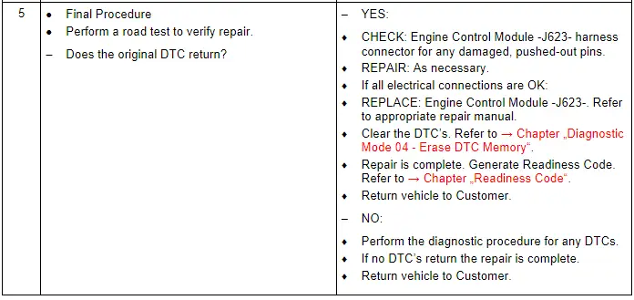
Ignition Coils With Power Output Stage, Checking
General Description
The ignition coil must transform the relatively low 12.0 V on-board vehicle voltage to the high ignition voltage required and supply the energy stored in that voltage to the spark plug. The functional principle of the ignition coil is relatively simple. It has a primary winding (small number of turns) and a secondary winding (lots of turns). The turn ratio between the number of primary and secondary winding turns determines the level of the voltage generated at the output. The Ignition Coils With Power Output Stage are plugged directly into the spark plug. This means that the ignition energy can be transferred directly to the spark plug with virtually zero power loss.
Special tools and workshop equipment required
- Multimeter.
- Wiring Diagram.
- Scan Tool.
- LED Test Lamp.
Test requirements
- Fuses OK.
- Battery voltage OK.
- Switch OFF all electrical and electronic accessories.
- Vehicles with automatic transmission, ensure the selector lever position is in "P".
- Vehicles with manual transmission, ensure the shifter lever position is in "N" with the parking brake applied.
- Coolant temperature: ≥ 80º C.
- Observe all safety precautions: → Chapter "Safety Precautions".
- View clean working conditions: → Chapter "Clean Working Conditions".
- For Hybrid vehicles, refer to: → Chapter "High Voltage System General Warnings".
Test Procedure